
Paint spraying equipment for new energy automobile parts

A technology for new energy vehicles and paint spraying equipment, applied in the direction of spraying devices, etc., can solve the problems of low work efficiency, affecting physical health, laborious and laborious, and achieve the effect of preventing uneven spraying

Pending Publication Date: 2021-06-11
廖军
View PDF0 Cites 7 Cited by
  • Summary
  • Abstract
  • Description
  • Claims
  • Application Information

AI Technical Summary

Problems solved by technology

[0004] In order to overcome the shortcomings of artificial painting that affects health, and the work efficiency is low and labor-intensive, the technical problem is to provide a new energy auto parts painting equipment that saves time and effort and improves work efficiency by self-painting.

Method used


Image

  • Paint spraying equipment for new energy automobile parts
  • Paint spraying equipment for new energy automobile parts
  • Paint spraying equipment for new energy automobile parts

Examples


Embodiment 1

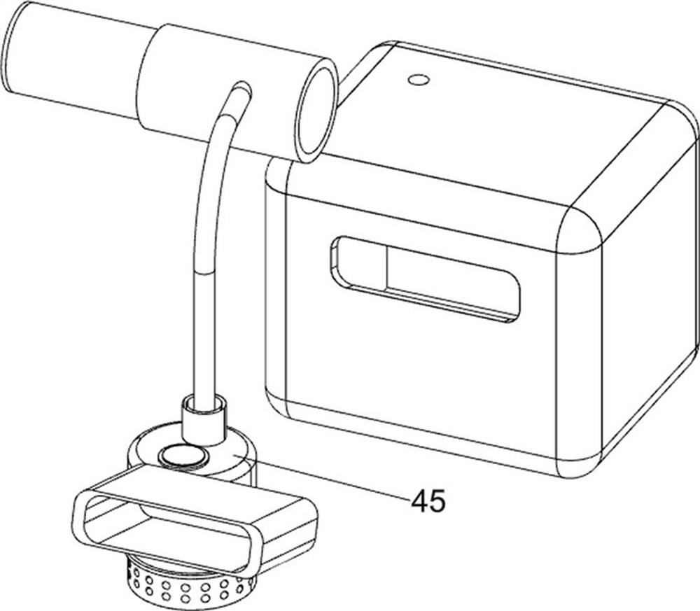
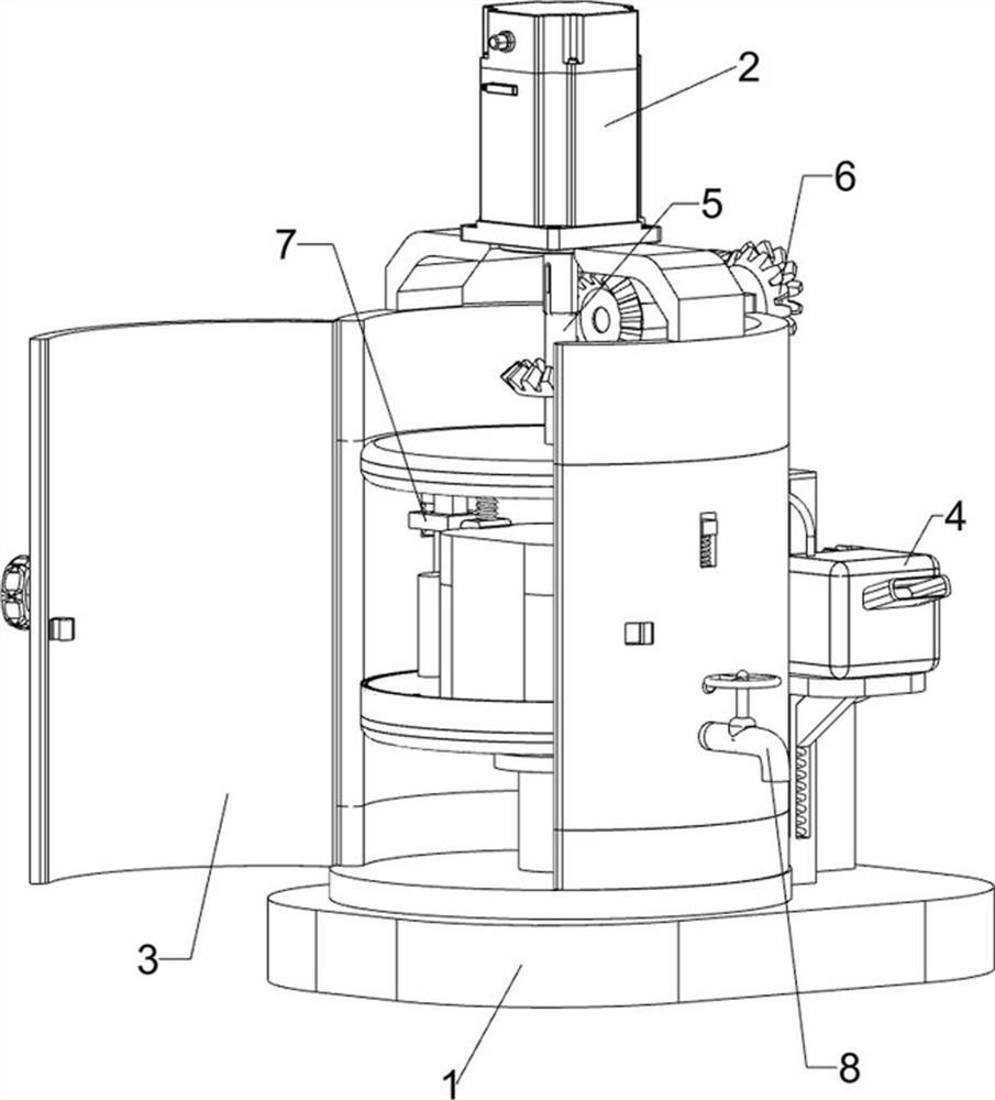
[0076] A new energy vehicle parts painting equipment, such as figure 1 As shown, it includes a bottom plate 1, a servo motor 2, a placement component 3, and a painting mechanism 4. The top front of the bottom plate 1 is provided with a placement component 3, the top of the placement component 3 is provided with a servo motor 2, and the rear side of the top of the bottom plate 1 is provided with a painting mechanism. 4.

[0077] When people want to paint the parts of the car, they put the parts on the 3 parts of the placement assembly, then put the paint into the 4 parts of the paint spraying mechanism, start the 4 parts of the paint spraying mechanism, and the 4 parts of the paint spraying mechanism spray paint on the parts, and people turn it manually Place the 3 parts of the assembly so that the paint is sprayed evenly, and after painting, close the 4 parts of the painting mechanism.

Embodiment 2

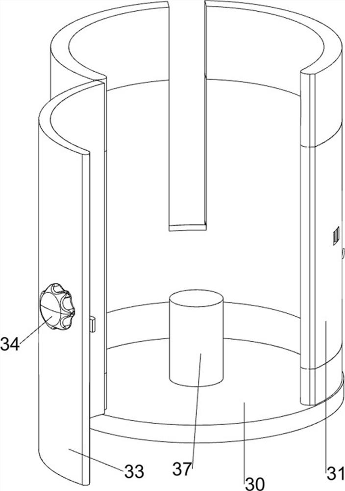
[0079] On the basis of Example 1, such as Figure 2-11 As shown, the placement assembly 3 includes a chassis 30, a protective plate 31, a hinge 32, a door 33, a handle 34, a lock 35, a first spring 36, a support column 37 and a rotating plate 38, and the top left side of the bottom plate 1 is provided with a There is an underframe 30, a support column 37 is arranged in the middle of the top of the underframe 30, a rotating plate 38 is connected to the top of the support column 37, and a protective plate 31 is arranged on the top of the underframe 30, and the top of the protective plate 31 is connected with the servo motor 2, and the protective plate 2 detachable hinges 32 are installed on the left side of the 31, and a detachable door 33 is installed between the left sides of the hinges 32. The lock 35 has two first springs 36 between the right side of the lock 35 and the protective plate 31 .

[0080] People put the parts on the rotary plate 38, then the door 33 is closed, w...


PUM


Abstract

The invention relates to paint spraying equipment, in particular to paint spraying equipment for new energy automobile parts. According to the technical aims, the paint spraying equipment for the new energy automobile parts is capable of automatically spraying paint, saving time and labor and improving the working efficiency. According to the technical scheme, the paint spraying equipment for new energy automobile parts comprises a bottom plate, a containing assembly, a servo motor and a paint spraying mechanism, wherein the containing assembly is arranged on one side of the bottom plate; the servo motor is arranged on the right side of the containing assembly; and the paint spraying mechanism is arranged on one side of the bottom plate. Through cooperation of the paint spraying mechanism and a rotating mechanism, people do not need to manually rotate parts, the rotating mechanism drives the parts to rotate, and the situation that paint is accumulated due to non-uniform spraying of the parts is prevented.

Description

technical field [0001] The invention relates to a painting equipment, in particular to a new energy automobile parts painting equipment. Background technique [0002] Cars are a necessary means of transportation for people to go out now. Almost every household is equipped with a private car. Cars can make people travel conveniently. There is no need to take a bus for a day, or squeeze the subway during peak hours. There are also many People like to travel by car. Cars can make people travel as soon as they say they want. There are many types of cars. There are also new energy vehicles, which do not need to burn oil, but only need to be charged, which greatly reduces the impact of car exhaust on the air. Pollution, when the car is manufactured, the parts required by the car need to be painted. Spraying can prolong the service life of the car and prevent the parts from corroding or rusting. The existing painting technology is that people hold spray guns and spray the parts. S...

Claims


Application Information

Patent Timeline
IPC IPC(8): B05B13/02B05B15/50
CPCB05B13/0228B05B15/50
Inventor 廖军
Owner 廖军
Learn More