Multifunctional automatic machining equipment for door and window metal parts

A metal parts, automatic processing technology, applied in the direction of metal processing, other manufacturing equipment/tools, manufacturing tools, etc., can solve the problem of reducing processing efficiency and achieve the effect of improving processing efficiency, high grinding quality, and simplified structure

Active Publication Date: 2021-06-11
春光五金有限公司
View PDF7 Cites 0 Cited by
  • Summary
  • Abstract
  • Description
  • Claims
  • Application Information

AI Technical Summary

Problems solved by technology

[0003]The above-mentioned processing steps often require punching machines, grinding machines and milling machines, as well as manual loading and manual transfer of semi-finished products between various equipments in sequence, greatly Reduced processing efficiency

Method used


Image

  • Multifunctional automatic machining equipment for door and window metal parts
  • Multifunctional automatic machining equipment for door and window metal parts
  • Multifunctional automatic machining equipment for door and window metal parts

Examples


Embodiment Construction

[0028] The technical solutions of the present invention will be clearly and completely described below in conjunction with the accompanying drawings. Apparently, the described embodiments are some of the embodiments of the present invention, but not all of them. Based on the embodiments of the present invention, all other embodiments obtained by persons of ordinary skill in the art without making creative efforts belong to the protection scope of the present invention.

[0029] In the description of the present invention, it should be noted that the terms "center", "upper", "lower", "left", "right", "vertical", "horizontal", "inner", "outer" etc. The indicated orientation or positional relationship is based on the orientation or positional relationship shown in the drawings, and is only for the convenience of describing the present invention and simplifying the description, rather than indicating or implying that the referred device or element must have a specific orientation, ...


PUM


Abstract

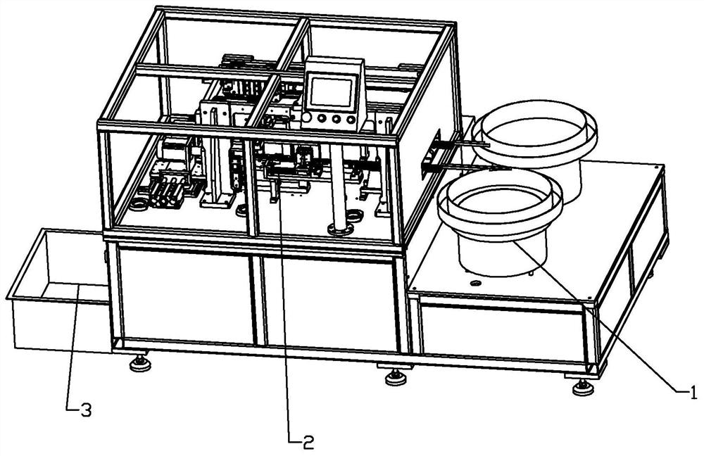
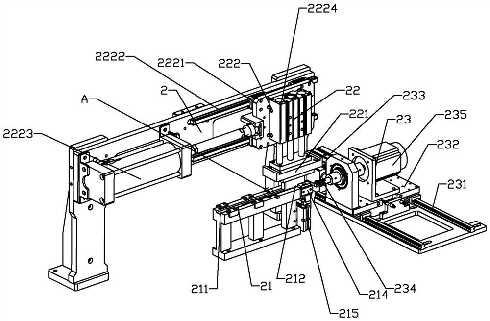
The invention relates to multifunctional automatic machining equipment for door and window metal parts. The multifunctional automatic machining equipment comprises a feeding device, a machining device and a discharging device, the feeding device places the metal parts on the machining device one by one, the machining device comprises a machining track, a punching mechanism and a milling mechanism, one end of the machining track serves as a machining starting end, the other end of the machining track serves as a machining tail end, and grinding pieces are arranged on the side walls of the two sides of the machining track correspondingly; and the punching mechanism comprises a punch base and a machining displacement mechanism, the punch base is provided with an arc punch used for punching the front end of the metal part, the arc punch moves along the machining track for pushing the metal part after punching and pushing the metal part, the grinding pieces carry out grinding in the moving process of the metal part until reaching the machining end, and the milling mechanism corresponds to the machining tail end in position and mills the plane, located at the machining tail end, of the rear end of the metal part. By the adoption of the scheme, the multifunctional automatic machining equipment for the door and window metal parts improves the machining efficiency and is simple in structure.

Description

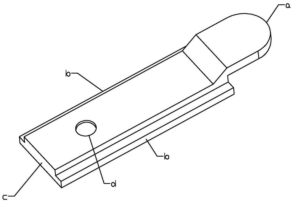
technical field [0001] The invention relates to a door and window processing equipment, in particular to a multifunctional automatic processing equipment for door and window metal parts. Background technique [0002] In the door and window structure, it often contains a variety of metal parts, such as figure 1 As shown, the metal part is a metal part with a locking function, which includes a bar-shaped body. During processing, the front end a of the bar-shaped body needs to be punched into an arc surface, and the two sides b of the bar-shaped body must be ground And the rear end c of the strip-shaped main body is milled with a plane, and the strip-shaped main body is punched with a round hole d before processing. [0003] The above-mentioned processing steps often require punching machines, grinding machines, and milling machines, as well as manual loading and manual transfer of semi-finished products between various devices in sequence, which greatly reduces processing eff...

Claims


Application Information

Patent Timeline
IPC IPC(8): B23P23/04B23Q7/00B65G47/14
CPCB23P23/04B23Q7/00B65G47/1421
Inventor 林普光
Owner 春光五金有限公司
Why Eureka
Try Eureka