Injection molding equipment for plastic production

An injection molding equipment and plastic technology, applied in the field of injection molding equipment for plastic production, can solve the problems affecting production speed, plastic quality, plastic surface quality, etc., to improve production efficiency and facilitate removal.

Pending Publication Date: 2021-06-11
邓义望
View PDF4 Cites 1 Cited by
  • Summary
  • Abstract
  • Description
  • Claims
  • Application Information

AI Technical Summary

Problems solved by technology

[0003] In the plastic production process, the molten plastic is injected into the mold of the plastic product by pressure, and various plastic parts are obtained by cooling and molding. The gas contained will affect the quality of the molded plastic; at the same time, the separation of the molded plastic and the cavity depends on the thimble to realize the ejection of the plastic, which affects the surface quality of the plastic; in the prior art, the injection molding process of plastic In the process, the separation of the mold core and the removal of the plastic are carried out separately, which seriously affects the production speed

Method used


Image

  • Injection molding equipment for plastic production
  • Injection molding equipment for plastic production
  • Injection molding equipment for plastic production

Examples


Embodiment

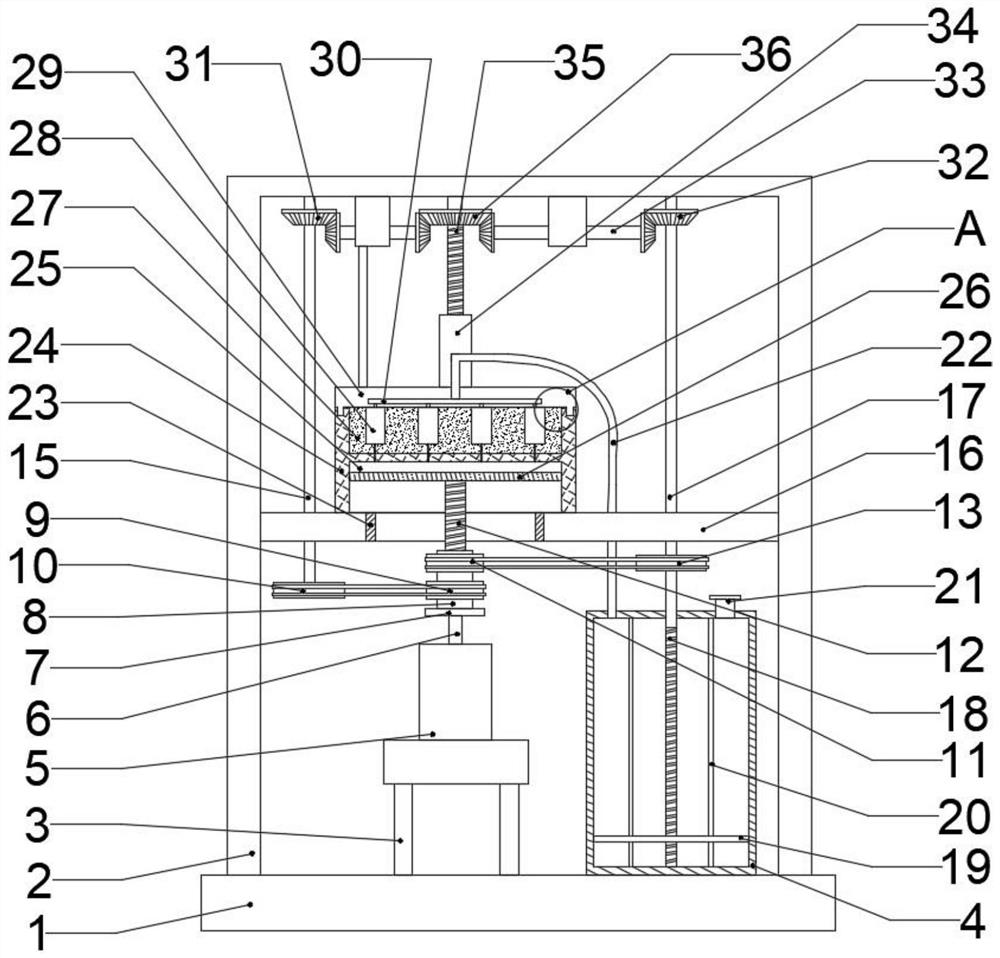
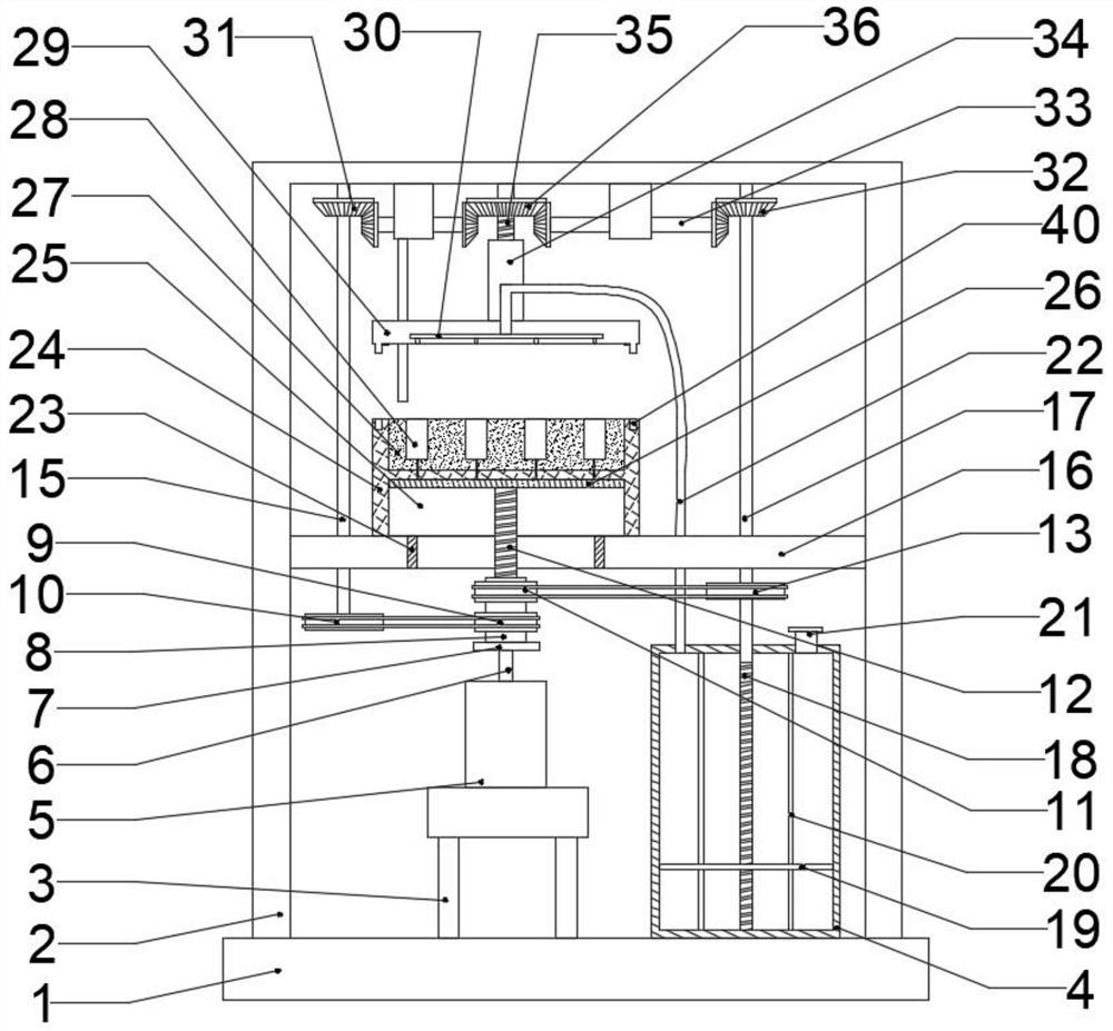
[0027] like Figure 1-5 As shown, an injection molding equipment for plastic production includes a base 1 for fixed support. The upper side of the base 1 is provided with a support frame 2 for fixing various structures. The motor base 3 of 5 and the storage chamber 4 for storing molten rubber, the upper side of the motor base 3 is provided with a drive motor 5, the upper end output end of the drive motor 5 is fixedly connected with the rotating shaft 6, and the rotating shaft 6 can be driven by the driving motor 5 Rotate, the upper end of rotating shaft 6 is fixedly connected with the turntable 7 that rotates thereupon, and the upper side of turntable 7 is fixedly connected with rotating cylinder 8, and rotating cylinder 8 rotates with the rotation of rotating disk 7, and the upper side of rotating cylinder 8 is provided with first The screw rod 12 can be controlled to move up and down by the rotary drum 8 .

[0028] The middle part of the support frame 2 is provided with a f...


PUM


Abstract

The invention belongs to the technical field of plastic production, and particularly relates to injection molding equipment for plastic production. The injection molding equipment comprises a base, wherein a supporting frame is arranged on the upper side of the base; a motor base and a storage chamber are sequentially arranged at the lower end of the supporting frame from left to right, and a driving motor is arranged on the upper side of the motor base; a rotating shaft is fixedly connected to the output end of the upper end of the driving motor, and a rotating disc is fixedly connected to the upper end of the rotating shaft; a rotating cylinder is fixedly connected to the upper side of the rotating disc, and a first screw rod is arranged on the upper side of the rotating cylinder; a fixing frame is arranged in the middle of the supporting frame, and a piston plate is fixedly connected to the end, penetrating through the fixing frame, of the first screw rod; an injection molding block is fixedly connected to the upper side of the middle of the fixing frame, an air cavity is formed in the lower portion of the injection molding block, and the piston plate is arranged in the air cavity; an assembling lower mold core is arranged on the upper portion of the injection molding block; and a plurality of mold cavities are formed in the assembling lower mold core. According to the injection molding equipment, the quality of molded plastic part can be improved, and the production speed can be greatly increased.

Description

technical field [0001] The invention belongs to the technical field of plastic production, in particular to an injection molding equipment for plastic production. Background technique [0002] It is mainly composed of carbon, oxygen, hydrogen, nitrogen and other organic or inorganic elements. The finished product is solid, and it is a molten liquid during the manufacturing process. Therefore, it can be heated to melt, pressurized to flow, and cooled to solidify. Formed into various shapes, this large and varied group of materials is called plastics. [0003] In the plastic production process, the molten plastic is injected into the mold of the plastic product by pressure, and various plastic parts are obtained by cooling and molding. The gas contained will affect the quality of the molded plastic; at the same time, the separation of the molded plastic and the cavity depends on the thimble to realize the ejection of the plastic, which affects the surface quality of the plast...

Claims


Application Information

Patent Timeline
Patent Type & Authority Applications(China)
IPC IPC(8): B29C45/46B29C45/58B29C45/26B29C45/66B29C45/43
CPCB29C45/46B29C45/58B29C45/26B29C45/66B29C45/43
Inventor 邓义望
Owner 邓义望
Why Eureka
Try Eureka