
Bushing assembly fixture for stabilizer bar product

A technology for assembling fixtures and stabilizer bars, which is applied in the field of auxiliary equipment for the bonding assembly line of stabilizer bar bushes, and can solve problems such as wear, reduced service life, and wear of stabilizer bar bushes

Pending Publication Date: 2021-06-11
GUANGZHOU HUADE AUTOMOBILE SPRING
View PDF0 Cites 0 Cited by
  • Summary
  • Abstract
  • Description
  • Claims
  • Application Information

AI Technical Summary

Problems solved by technology

[0002] In the prior art, the stabilizer bar and the bushing of the stabilizer bar are fixed by metal clamps, and there will be abnormal noises between the stabilizer bar and the bushing during driving, especially at low temperature due to the friction of the bushing of the stabilizer bar. The hardening of the rubber leads to greater abnormal noise and wear of the stabilizer bar bushing, which reduces the service life. It is now necessary to make improvements to the above problems to solve the problems of abnormal noise and bush wear. For this reason, in the stabilizer bar Or add one or more adhesives to the bushing, use a certain clamping force to hold the pressure at a specific temperature for a certain period of time, so that the adhesive reacts to bond the stabilizer bar and the bushing together, Therefore, a fixture suitable for the stabilizer bar bushing bonding assembly line is needed to ensure the overall bonding process of the bushing, solve the problem of abnormal noise after the stabilizer bar is loaded, and improve the service life of the stabilizer bar

Method used


Image

  • Bushing assembly fixture for stabilizer bar product
  • Bushing assembly fixture for stabilizer bar product
  • Bushing assembly fixture for stabilizer bar product

Examples


Embodiment Construction

[0014] The following will clearly and completely describe the technical solutions in the embodiments of the present invention with reference to the accompanying drawings in the embodiments of the present invention. Obviously, the described embodiments are only some, not all, embodiments of the present invention. Based on the embodiments of the present invention, all other embodiments obtained by persons of ordinary skill in the art without making creative efforts belong to the protection scope of the present invention.

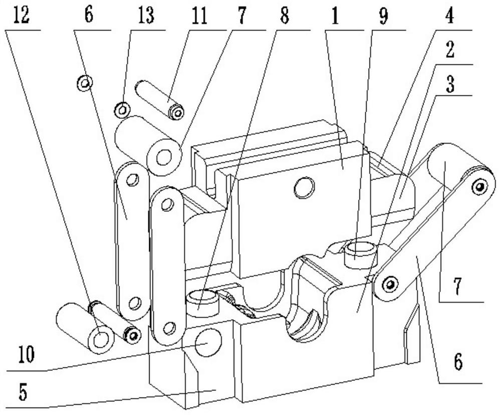
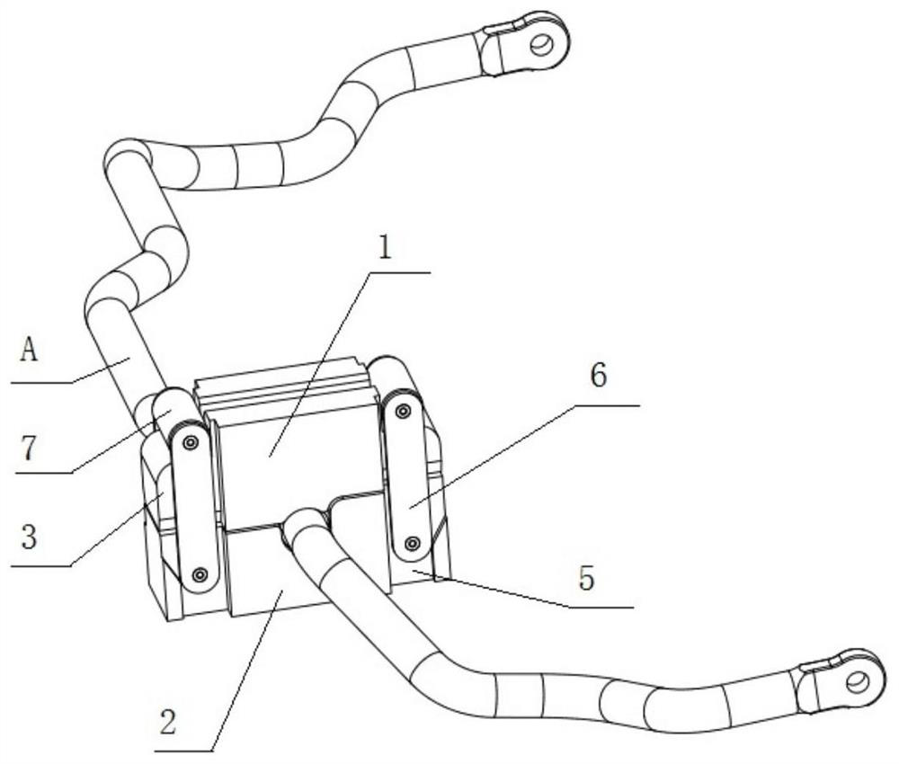
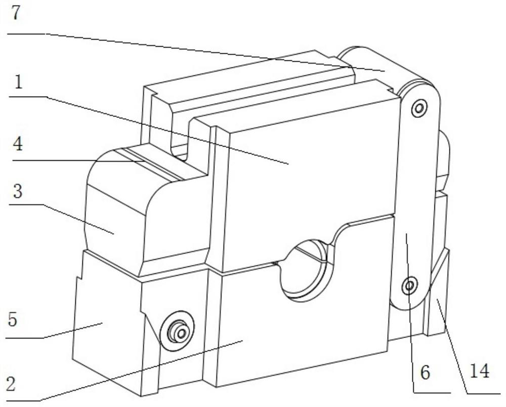
[0015] see Figure 1-3 , the present invention provides a technical solution: a bush fitting fixture for stabilizer bar products, including an upper mold 1, a lower mold 2 and a connecting arm 6, the upper mold 1 and the lower mold 2 are connected with the bushing Matching, the upper mold 1 and the lower mold 2 are respectively put into half of the bushings for matching, and the two sides of the upper mold 1 are processed with overlapping side ears 3, and the ...


PUM


Abstract

The invention discloses a bushing assembly fixture for a stabilizer bar product. The bushing assembly fixture comprises an upper die, a lower die and connecting arms, wherein the upper die and the lower die are matched with a bushing, the upper die and the lower die are arranged in half of the bushing to be matched in an involution manner, and lap joint side lugs are machined at the two sides of the upper die; and an anti-disengaging groove is formed in each lap joint side lug, extending-out steps are machined at the two sides of the lower die and rotationally matched with one ends of the connecting arms, the other ends of the connecting arms are rotationally matched with a locking rotating roller, the locking rotating roller is matched with the anti-disengaging grooves, a first guide column and a second guide column are further arranged on the lower die, and the first guide column and the second guide column are located at the two sides of the lower die respectively. The stabilizer bar and the bushing assembly clamp have a good heat preservation effect, the bonding temperature of the bushing can be conveniently controlled, the device is reasonable in structural design, high in strength and capable of being repeatedly used, the problem of abnormal sound after a stabilizer bar is loaded is solved by bonding the bushing through the assembly clamp, and meanwhile the service life of the stabilizer bar is prolonged.

Description

technical field [0001] The invention relates to the field of auxiliary equipment for a stabilizer bar bush bonding assembly production line, in particular to a bush fitting fixture for stabilizer bar products. Background technique [0002] In the prior art, the stabilizer bar and the bushing of the stabilizer bar are fixed by metal clamps, and there will be abnormal noises between the stabilizer bar and the bushing during driving, especially at low temperature due to the friction of the bushing of the stabilizer bar. The hardening of the rubber leads to greater abnormal noise and wear of the stabilizer bar bushing, which reduces the service life. It is now necessary to make improvements to the above problems to solve the problems of abnormal noise and bush wear. For this reason, in the stabilizer bar Or add one or more adhesives to the bushing, use a certain clamping force to hold the pressure at a specific temperature for a certain period of time, so that the adhesive react...

Claims


Application Information

Patent Timeline
IPC IPC(8): B29C65/78B29C65/56B29C65/48B29C65/24
CPCB29C65/7805B29C65/56B29C65/4835B29C65/245
Inventor 黄春阳卢伟刘浩均黎周君
Owner GUANGZHOU HUADE AUTOMOBILE SPRING
Learn More