
Launching device based on synchronous belt

A technology of launching device and synchronous belt, which is applied in launching/drag transmission device, using a device that measures the time required to move a certain distance, re-radiation of electromagnetic waves, etc. problem, to achieve the effect of simple device structure, low manufacturing cost and easy control

Pending Publication Date: 2021-06-11
SOUTH CHINA UNIV OF TECH +1
View PDF0 Cites 0 Cited by
  • Summary
  • Abstract
  • Description
  • Claims
  • Application Information

AI Technical Summary

Problems solved by technology

There are also many advances in the research on the take-off method of UAVs, but there are many problems in controlling the stability of the launch, such as the instability of the launch speed and the vibration generated during launch, which will greatly affect the take-off of the UAV. The state of the flight will cause instability to the flight, and damage the UAV if it is serious.

Method used


Image

  • Launching device based on synchronous belt
  • Launching device based on synchronous belt
  • Launching device based on synchronous belt

Examples


Embodiment Construction

[0020] The present invention will be further described below in conjunction with drawings and embodiments.

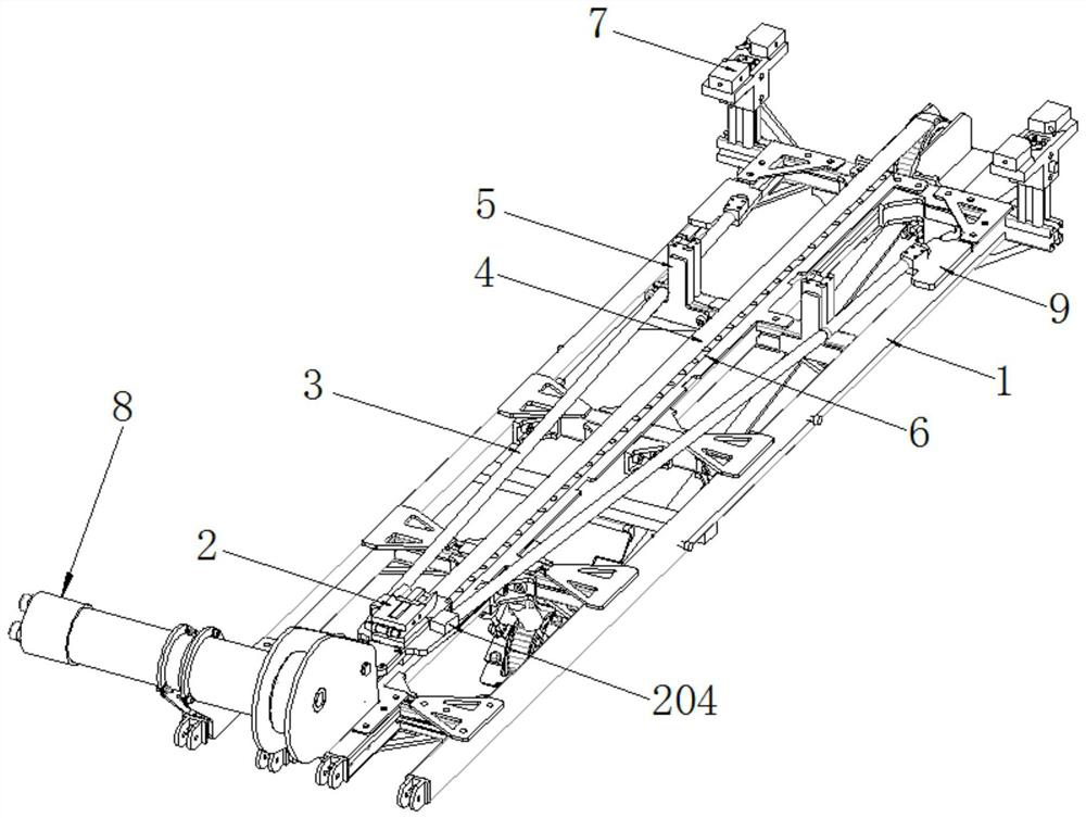
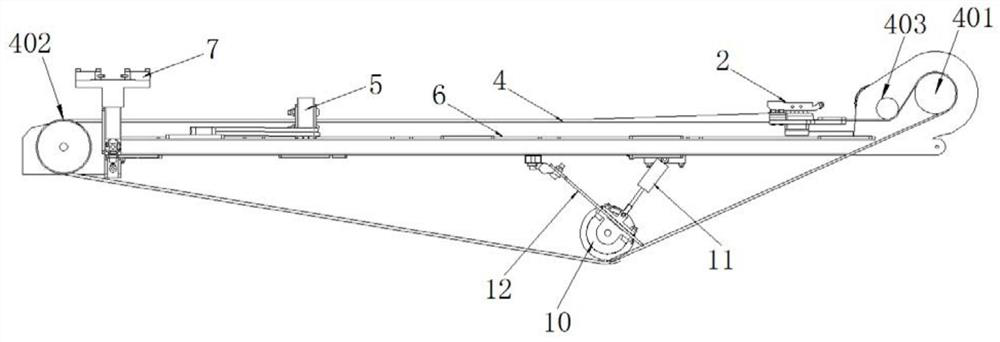
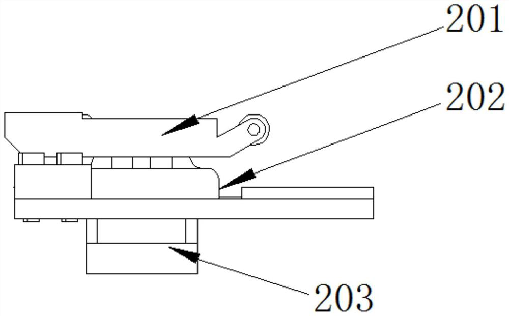
[0021] like Figures 1 to 3 A launcher based on a synchronous belt shown includes a frame 1, a synchronous belt 4, a driving wheel 401, a driven wheel 402, a DC brushless motor 8, a guide rail 6 and a slider type support 2, and the driving wheel 401 and Driven wheels 402 are mounted on the rear end and the front end of the frame 1 respectively, and the driving wheel 401 is connected with the power output shaft of the DC brushless motor 8, and the DC brushless motor 8 provides power for the driving wheel 401, and the two synchronous belts 4 The ends are respectively connected with the driving wheel 401 and the driven wheel 402, the DC brushless motor 8 drives the driving wheel 401 to rotate, the driving wheel 401 and the driven wheel 402 cooperate with each other, thereby driving the synchronous belt 4 to move, the guide rail 6 is installed on the frame 1, and This guid...


PUM


Abstract

The transmitting device comprises a frame, the synchronous belt, a driving wheel, a driven wheel, a direct current brushless motor, a guide rail and a sliding block type support, the driving wheel and the driven wheel are installed at the rear end and the front end of the frame respectively, the driving wheel is connected with a power output shaft of the direct current brushless motor, and the guide rail is connected with the sliding block type support. The two ends of the synchronous belt are connected with the driving wheel and the driven wheel respectively, and the guide rail is installed on the frame and located under the launching section of the synchronous belt. An edge pressing wheel is arranged at the rear end of the frame and is tightly pressed on the synchronous belt, so that the transmitting section of the synchronous belt is parallel to the guide rail; the sliding block type support is fixed to the transmitting section of the synchronous belt, and the lower end of the sliding block type support is in sliding connection with the guide rail. The sliding block type support of the launching device is connected with the synchronous belt, the edge pressing wheel is tightly pressed on the synchronous belt to enable the launching section of the synchronous belt to be parallel to the guide rail, the edge pressing wheel enables the synchronous belt to operate more stably, and therefore the unmanned aerial vehicle is stably launched through the sliding block support, and the device is simple in structure, easy to control and low in manufacturing cost.

Description

technical field [0001] The invention relates to a launching platform of an unmanned aerial vehicle, in particular to a launching device based on a timing belt. Background technique [0002] With the country's strategic layout, drones are gradually moving from military to civilian use. Fixed-wing UAVs have more advantages than rotary-wing UAVs, such as faster speed and longer range. Fixed-wing drones are widely used in government agencies and business sectors. The drone market has also been rejuvenated. There are also many advances in the research on the take-off method of UAVs, but there are many problems in controlling the stability of the launch, such as the instability of the launch speed and the vibration generated during launch, which will greatly affect the take-off of the UAV. If the state of the flight is not stable, it will cause instability to the flight, or damage the UAV if it is serious. Therefore, a sufficiently stable, economical and practical launching de...

Claims


Application Information

Patent Timeline
IPC IPC(8): B64F1/04G01P3/68
CPCB64F1/04G01P3/68
Inventor 张东孟峻霆梁庆铧苏锴南陈泯霖谭雨欣
Owner SOUTH CHINA UNIV OF TECH
Learn More