Hydraulically-driven rotary casing shoe with multi-stage power system

A power system and hydraulic drive technology, applied in the direction of casing, drilling pipe, drilling equipment, etc., can solve the problems of increasing cost, unable to realize casing rotation, increasing operating time, etc.

Active Publication Date: 2021-06-11
北京佰文恒新能源服务有限公司
View PDF10 Cites 0 Cited by
  • Summary
  • Abstract
  • Description
  • Claims
  • Application Information

AI Technical Summary

Problems solved by technology

If the process of running the casing is not smooth, it will increase the operating time and increase the cost
In order to promote the casing to run smoothly to the target depth, sometimes the casing is rotated mechanically at the wellhead to achieve reaming through difficult well sections caused by diameter shrinkage, collapse, etc., but this method has great limitations. Casing rotation is often not possible due to torque limitations of casing connection threads or surface equipment

Method used


Image

  • Hydraulically-driven rotary casing shoe with multi-stage power system
  • Hydraulically-driven rotary casing shoe with multi-stage power system
  • Hydraulically-driven rotary casing shoe with multi-stage power system

Examples


Embodiment

[0050] The present invention will be further described below in conjunction with the accompanying drawings.

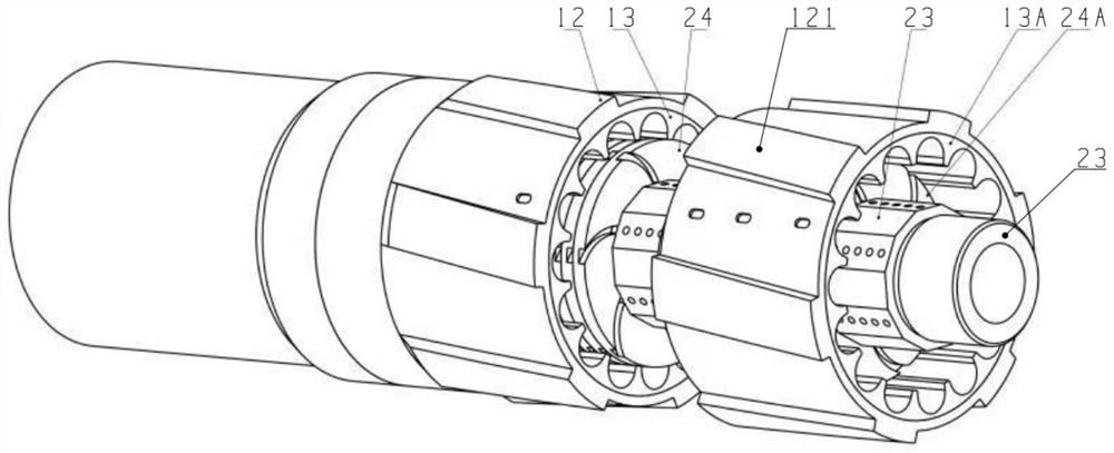
[0051] Such as Figure 1-3 As shown, the multi-stage power system hydraulically driven rotary casing shoe provided by this embodiment includes:

[0052] A rotating combination, a non-rotating combination and a bearing system, the rotating combination is rotatably connected to the outside of the non-rotating combination through the bearing system, and the rotating combination and the non-rotating combination form a multi-stage rotating structure.

[0053] The working principle of the present invention is as follows: the present invention provides a multi-stage power system hydraulically driven rotating casing shoe. When in use, one end of the non-rotating combination is connected to the main body of the casing, a multi-stage rotor is arranged in the rotating combination, and a multi-stage stator is arranged in the non-rotating combination. , when the lower casing encou...


PUM


Abstract

The invention discloses a hydraulically-driven rotary casing shoe with a multi-stage power system. The Hydraulically-driven rotary casing shoe comprises a rotating combination, a non-rotating combination and a bearing system, wherein the rotating combination is rotatably connected to the outer side of the non-rotating combination through the bearing system, and the rotating combination and the non-rotating combination form a multi-stage rotating structure. According to the hydraulically-driven rotary casing shoe, a rotor rotational flow cylinder is pushed by rotational flow which is generated when fluid flows through a stator rotational flow piece, then a redressing guide shoe is driven to rotate so as to pass through a well section with diameter shrinkage and the like which are not beneficial for a casing to pass, the target that the casing smoothly descends to the target depth is achieved, and the multi-stage rotational flow rotor and stator combination is arranged, so that the torque is increased, and the effectiveness of the device is increased.

Description

technical field [0001] The invention relates to the technical field of oilfield cementing operations, in particular to a hydraulically driven rotary casing shoe of a multistage power system. Background technique [0002] In the process of casing running in oil or natural gas well completion, it is very important to successfully run the production casing to the predetermined depth at one time to complete the predetermined goal. During the casing running process, due to various reasons such as formation stability and wellbore trajectory, there will be many factors that are not conducive to the casing running in place, such as wellbore shrinkage, collapse, and high frictional resistance. If the descent is less than the predetermined depth, the resources of the target layer cannot be exploited. If the process of running into the casing is not smooth, it will cause increased operating time and increased costs. In order to promote the casing to run smoothly to the target depth, ...

Claims


Application Information

Patent Timeline
Patent Type & Authority Applications(China)
IPC IPC(8): E21B17/14E21B7/20
CPCE21B17/14E21B7/208
Inventor 魏萍徐希良
Owner 北京佰文恒新能源服务有限公司
Why Eureka
Try Eureka