Vibrating wire type surface strain gauge and use method thereof

A strain gauge and vibrating wire technology, which is applied in the field of civil engineering testing instruments, can solve problems such as falling off and poor device stability, and achieve the effects of avoiding falling, improving the scope of application, and improving stability

Active Publication Date: 2021-06-11
NANJING INST OF TECH
View PDF12 Cites 0 Cited by
  • Summary
  • Abstract
  • Description
  • Claims
  • Application Information

AI Technical Summary

Problems solved by technology

[0003] The purpose of the present invention is to provide a vibrating wire surface strain gauge and its use method, to solve the existing problems: the existing device is easy to fall off due to the stress change of concrete and steel bars, and the stability of the device is relatively poor

Method used


Image

  • Vibrating wire type surface strain gauge and use method thereof
  • Vibrating wire type surface strain gauge and use method thereof
  • Vibrating wire type surface strain gauge and use method thereof

Examples


Embodiment 1

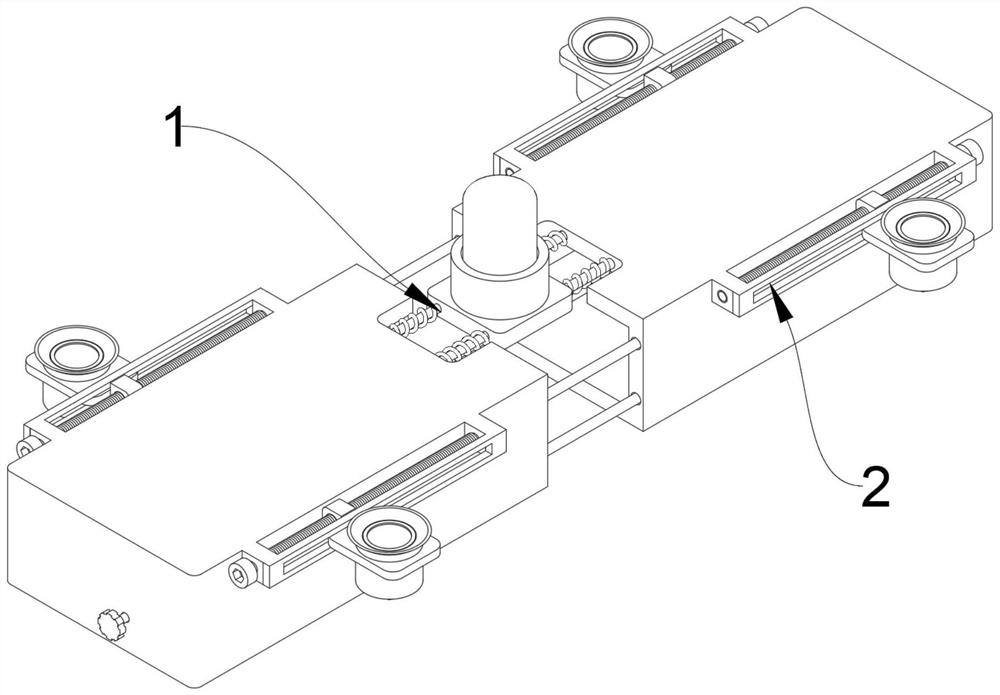
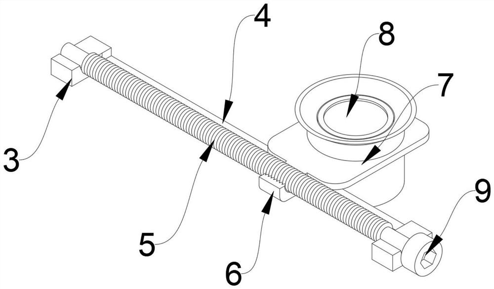
[0041] see Figure 1-6 As shown, the present invention is a vibrating wire surface strain gauge, comprising a strain gauge body 1, and both sides of both ends of the strain gauge body 1 are fixed with a fixing mechanism 2, and the fixing mechanism 2 includes a slide rail 3, and the inside of the slide rail 3 is provided with There is a working chamber 4, and the inside of the working chamber 4 is slidingly connected with a transmission block 6, and one end of the transmission block 6 is fixed with a fixed plate 7, and an adsorption mechanism 8 is installed inside the fixed plate 7, and the middle position of the working chamber 4 is rotatably connected with a threaded rod 5;

[0042] Here, one end of the threaded rod 5 is fixed with a transmission cap 9, and the transmission cap 9 can be one of an outer hexagonal cap or an inner hexagonal cap;

[0043] When in use, the transmission cap head 9 is rotated by a wrench, and the threaded rod 5 will be driven to rotate when the tra...

Embodiment 2

[0056] A method for using a vibrating wire surface strain gauge is disclosed on the basis of Embodiment 1, the steps of which are as follows:

[0057] Step 1: Turn the transmission cap 9 with a wrench during use. When the transmission cap 9 rotates, it will drive the threaded rod 5 to rotate, because the transmission block 6 and the threaded rod 5 are connected by threads, and the transmission block 6 is slidingly connected in the working chamber 4, when the threaded rod 5 rotates, it will drive the transmission block 6 to slide inside the working chamber 4, so that the position of the fixed plate 7 can be adjusted through the transmission block 6, so that the device can be fixed on concrete with different shapes, and the steel bars inside the concrete Testing, thus greatly improving the scope of application of the device;

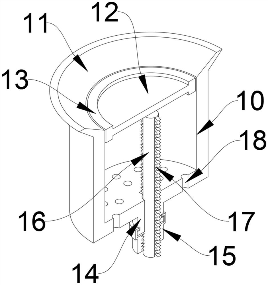
[0058] Step 2: move the first casing 19 and the second casing 20 to one end of the concrete, so that the horn gasket 11 is in contact with the surface of ...


PUM


Abstract

The invention discloses a vibrating wire type surface strain gauge and a use method thereof, and relates to the technical field of civil engineering test instruments. The strain gauge comprises a strain gauge body, fixing mechanisms are fixed to the two sides of the two ends of the strain gauge body, each fixing mechanism comprises a sliding rail, a working cavity is formed in each sliding rail, a transmission block is slidably connected into each working cavity, and a fixing plate is fixed to one end of each transmission block. The strain gauge can be firmly fixed to the surface of concrete through cooperation of all accessories, the strain gauge is effectively prevented from falling off due to stress changes of the concrete and reinforcing steel bars, and the stability of the strain gauge is greatly improved; and the strain gauge can be fixed to the concrete in different shapes by arranging the fixing mechanism, and the reinforcing steel bars in the concrete are detected, so that the application range of the strain gauge is greatly expanded, the stress of the concrete and the reinforcing steel bars can be simply detected, and an operator can be automatically warned when the stress fluctuation of the concrete and the reinforcing steel bars is large.

Description

technical field [0001] The invention belongs to the technical field of civil engineering testing instruments, in particular to a vibrating wire surface strain gauge and a using method thereof. Background technique [0002] At present, the method of measuring steel bar strain by using the vibrating wire steel bar strain gauge designed by the resonance principle is widely used. During the use of this method, a lot of improvements have been made for different conditions of use, which greatly improves the measurement accuracy and practicability. The strain gauge design is simple and can meet certain engineering measurement needs, but the existing device is easy to fall off due to the stress change of concrete and steel bars, the stability of the device is poor, and the scope of application is small. It is necessary to detect the stress of concrete and steel bars It is difficult to operate, and the operator cannot be warned in time when the stress fluctuation of concrete and stee...

Claims


Application Information

Patent Timeline
Patent Type & Authority Applications(China)
IPC IPC(8): G01L1/10G01B21/32
CPCG01L1/10G01L1/106G01B21/32
Inventor 支有冉李果
Owner NANJING INST OF TECH
Why Eureka
Try Eureka