
Vibration device and instrument detection device

A technology of vibrating devices and moving parts, applied in measuring devices, calibration/testing of force/torque/power measuring instruments, instruments, etc., can solve problems such as low work efficiency, high labor intensity, and affecting the accuracy of pressure gauges, and achieve Save time, improve work efficiency, and reduce measurement errors

Active Publication Date: 2021-06-11
金仪计量科技(苏州)有限公司
View PDF4 Cites 0 Cited by
  • Summary
  • Abstract
  • Description
  • Claims
  • Application Information

AI Technical Summary

Problems solved by technology

[0004] However, the current pressure gauge verification and calibration process still adopts traditional manual operation. The tapping process is also the measurement personnel hitting the case with their hands, which is labor-intensive and low-efficiency. Affect the accuracy of pressure gauge calibration

Method used


Image

  • Vibration device and instrument detection device
  • Vibration device and instrument detection device
  • Vibration device and instrument detection device

Examples


Embodiment Construction

[0037] In order to have a clearer understanding of the above objects, features and advantages of the present invention, the present invention will be further described in detail below in conjunction with the accompanying drawings and specific embodiments. It should be noted that, in the case of no conflict, the embodiments of the present application and the features in the embodiments can be combined with each other.

[0038] In the following description, many specific details are set forth in order to fully understand the present invention, but the present invention can also be implemented in other ways different from those described here. Therefore, the protection scope of the present invention is not limited by the specific details disclosed below. EXAMPLE LIMITATIONS.

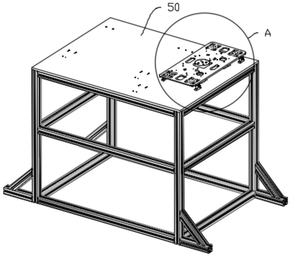
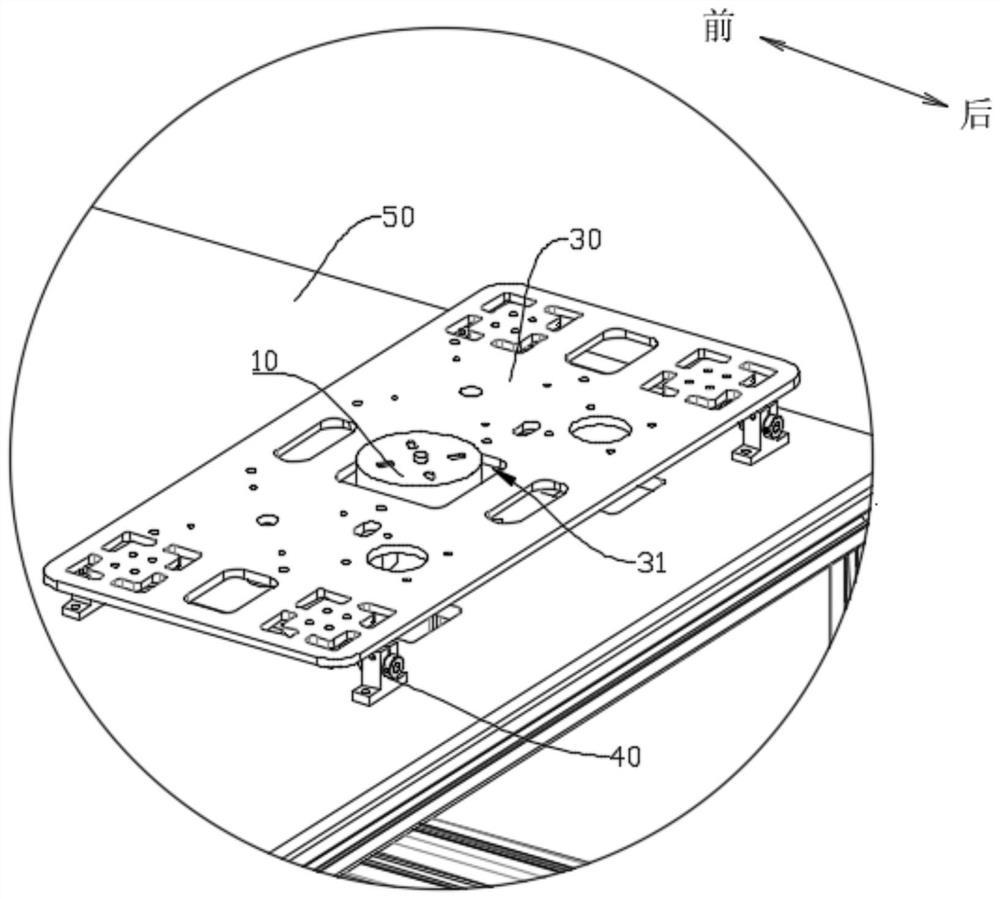
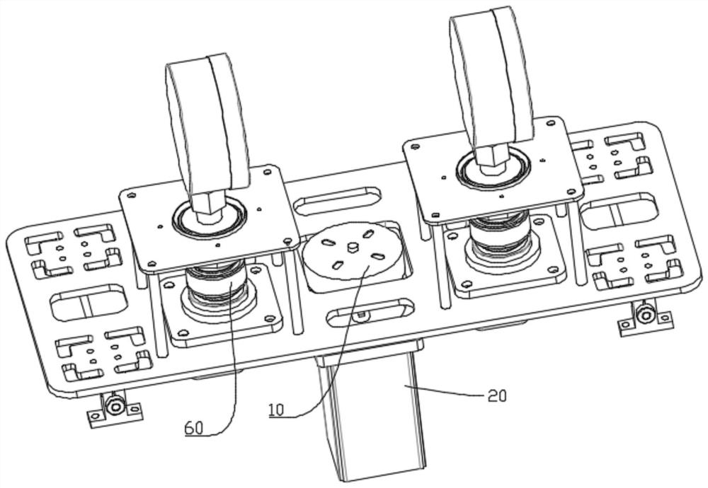
[0039] Refer below Figure 1 to Figure 12 Some embodiments according to the invention are described.

[0040] This embodiment provides a vibrating device, which can be applied to equipment that needs tapp...


PUM

PropertyMeasurementUnit
torqueaaaaaaaaaa

Abstract

The invention relates to the field of instrument verification and particularly relates to a vibration device. The vibration device comprises a cam, a power module, a driven part and a reset module, wherein the power module is used for driving the cam to rotate around the rotation center of the cam; the reset module is arranged on the driven part, and the reset module is used for resetting the driven part; when the cam rotates, the driven piece can do reciprocating motion in the linear direction. The vibration device is advantaged in that the vibration device is applied to calibration of the pressure gauge, the pressure gauge can be installed on the driven member through the calibration joint, and the vibration device enables the driven member to vibrate to drive the pressure gauge to vibrate through the cooperation of the parts, and thereby a pointer of the pressure gauge to be calibrated is made to overcome the internal mechanical friction and mechanical resistance, and therefore, tapping is replaced, the measurement error is reduced, and working efficiency is improved.

Description

technical field [0001] The invention relates to the field of instrument verification, in particular to a vibration device and an instrument detection device. Background technique [0002] In the current field of instrumentation calibration technology, completely independent pressure gauge calibration equipment has not yet matured and been widely used, which is mainly limited by the external dimensions, joint sizes, and range ranges of pressure gauges with various specifications. , as well as complex and cumbersome calibration process and multiple standard calibration methods. [0003] Due to the mechanical friction and mechanical resistance of the internal transmission mechanism of the pressure gauge, the indication of the mechanical pressure gauge is often inaccurate. Therefore, after the verification equipment is pressurized to the desired value, it is necessary to tap the pressure gauge case to make the pointer go to the point where it should actually reach. position, re...

Claims


Application Information

Patent Timeline
Patent Type & Authority Applications(China)
IPC IPC(8): G01L25/00G01L27/00
CPCG01L25/00G01L27/005
Inventor 陈泽芸吴义钱志刚范长湘郭靖
Owner 金仪计量科技(苏州)有限公司
Learn More