Electronic transformer verifying device

A technology for electronic transformers and calibration devices, which is applied to measuring devices, instruments, and measuring electrical variables, etc., can solve the problems of lack of digital interfaces and electronic transformer calibration, and achieve the effect of improving efficiency

Inactive Publication Date: 2014-05-07
HARBIN INST OF TECH +2
View PDF4 Cites 0 Cited by
  • Summary
  • Abstract
  • Description
  • Claims
  • Application Information

AI Technical Summary

Problems solved by technology

[0005] The present invention aims to solve the problem that the traditional transformer calibration device lacks a corresponding digital interface and cannot calibrate the electronic transformer

Method used


Image

  • Electronic transformer verifying device
  • Electronic transformer verifying device
  • Electronic transformer verifying device

Examples


specific Embodiment approach 1

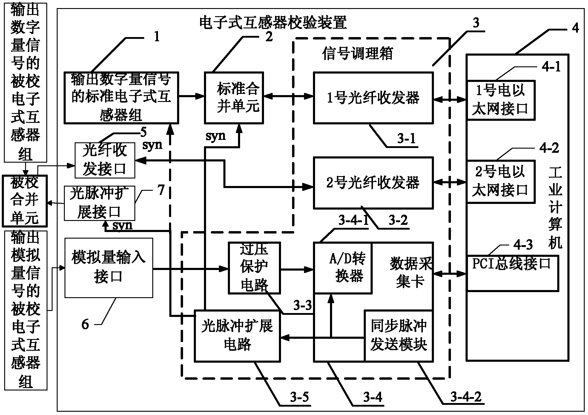
[0017] Specific implementation mode 1. Combination figure 1 Specifically explain this embodiment, an electronic transformer calibration device described in this embodiment, the calibration device includes: a standard electronic transformer group 1 that outputs digital signals, a standard merging unit 2, and a signal conditioning box 3 , industrial computer 4, optical fiber transceiver interface 5, analog input interface 6 and optical pulse expansion interface 7, the signal conditioning box 3 includes: No. 1 optical fiber transceiver 3-1, No. 2 optical fiber transceiver 3-2, overvoltage protection Circuit 3-3, data acquisition card 3-4 and optical pulse expansion circuit 3-5; the data acquisition card 3-4 includes: A / D conversion module 3-4-1 and synchronous pulse sending module 3-4-2 ; The industrial computer 4 is configured with No. 1 electrical Ethernet interface 4-1, No. 2 electrical Ethernet interface 4-2 and PCI bus interface 4-3, and the optical fiber sent by the standar...

specific Embodiment approach 2

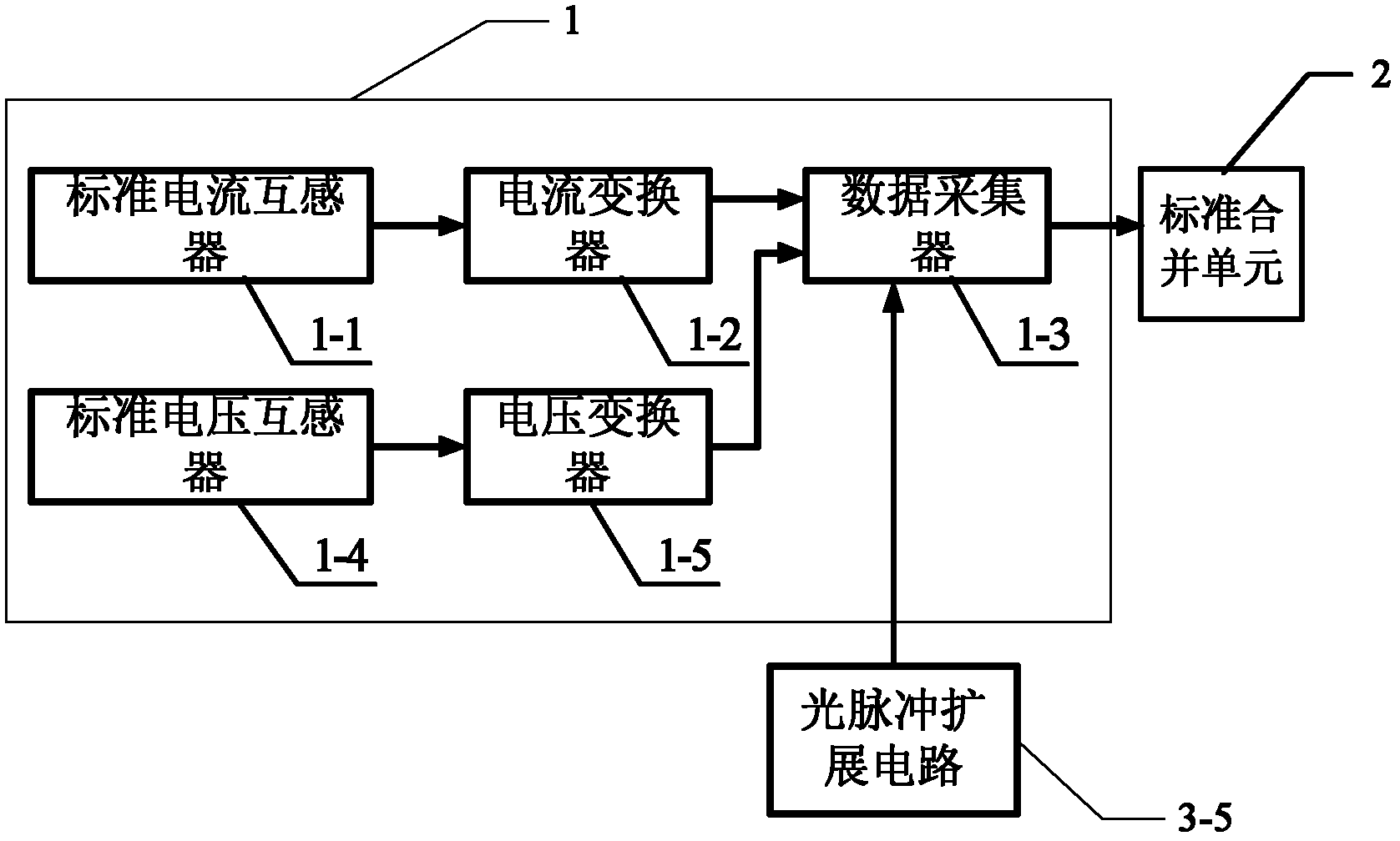
[0022] Specific embodiment two, combine figure 2 Describe this embodiment in detail. The difference between this embodiment and the electronic transformer calibration device described in Embodiment 1 is that the standard electronic transformer group 1 that outputs digital signals includes: standard current transformer 1-1, current transformer 1-2, standard voltage transformer 1-4, voltage transformer 1-5 and data collector 1-3,

[0023] The current signal output terminal of the standard current transformer 1-1 is connected to the current signal input terminal of the current converter 1-2, and the analog current data output terminal of the current converter 1-2 is connected to the analog current data input terminal of the data collector 1-3 ; The voltage signal output terminal of the standard voltage transformer 1-4 is connected to the voltage signal input terminal of the voltage converter 1-5, and the analog voltage data output terminal of the voltage converter 1-5 is connect...

specific Embodiment approach 3

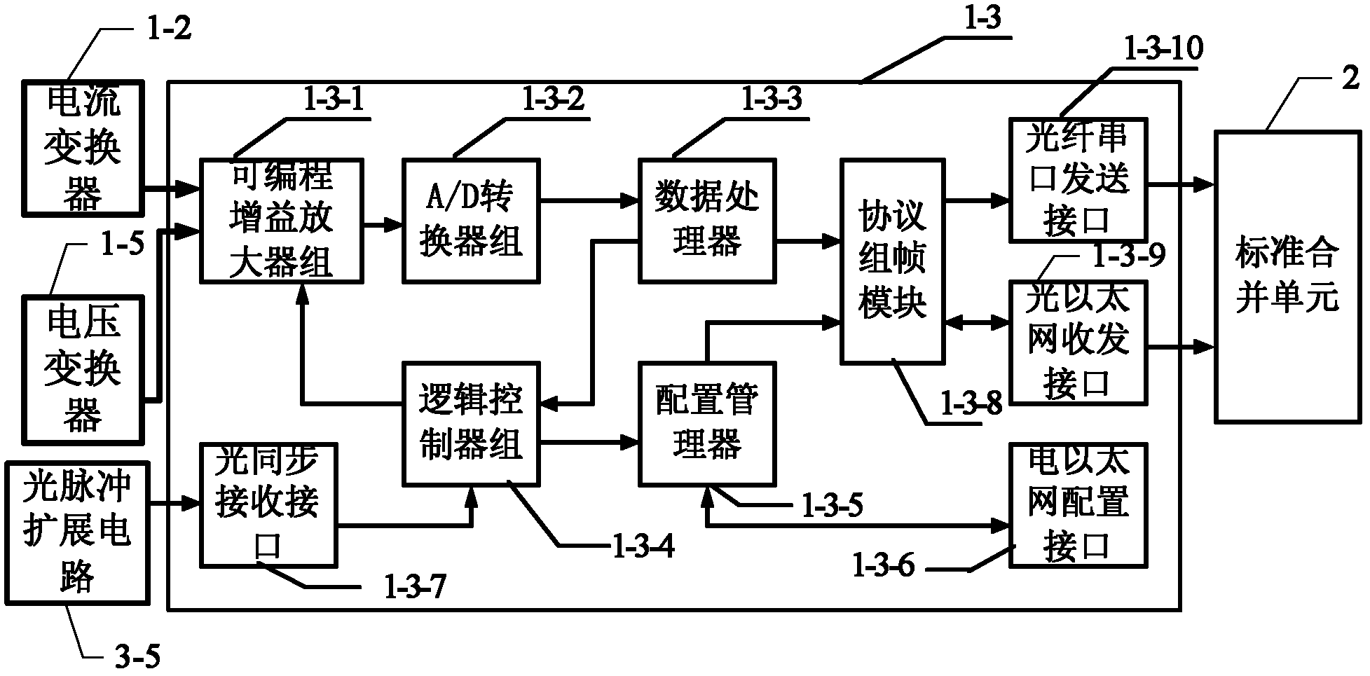
[0024] Specific embodiment three, combine image 3This embodiment is described in detail. The difference between this embodiment and the second embodiment is that the data collector 1-3 includes: a programmable gain amplifier group 1-3-1, an A / D converter group 1-3- 2. Data processor 1-3-3, logic controller group 1-3-4, configuration manager 1-3-5, electrical Ethernet configuration interface 1-3-6, optical synchronization receiving interface 1-3-7 , protocol framing module 1-3-8, optical Ethernet transceiver interface 1-3-9 and optical fiber serial port transmission interface 1-3-10;

[0025] The analog current signal of the current converter 1-2 and the analog voltage signal of the voltage converter 1-5 are simultaneously sent to the programmable gain amplifier group 1-3-1, and the analog current signal received by the programmable gain amplifier group 1-3-1 The signal is amplified according to its initial gain and sent to the A / D converter group 1-3-2, and the A / D converter...


PUM


Abstract

The invention relates to an electronic transformer verifying device. The electronic transformer verifying device aims to solve the problems that the conventional transformer verifying device lacks a corresponding digital interface and cannot verify an electronic transformer. The electronic transformer verifying device comprises a standard electronic transformer group, a standard merging unit, a signal conditioning box, an industrial computer, a merging unit interface, an analog quantity input interface and an optical pulse expansion interface. The signal conditioning box comprises a No.1 optical fiber transceiver, a No.2 optical fiber transceiver, an over-voltage protection circuit, a data acquisition card and an optical pulse expansion circuit; the industrial computer is provided with a No.1 electric ethernet port, a No.2 electric ethernet port and a peripheral component interconnect (PCI) bus interface; and the standard electronic transformer group can consist of a single standard electronic transformer or a plurality of standard electronic transformers according to different application occasions. The electronic transformer verifying device is applied in the field of verification of transformers for electric power systems.

Description

technical field [0001] The invention relates to the field of electric equipment testing, in particular to an electronic transformer calibration device. Background technique [0002] The traditional transformer calibration device consists of a standard transformer, a measured transformer and a transformer calibrator. Among them, the transformer calibrator generally adopts the principle of electrotechnical difference measurement, that is, the measured transformer and the standard transformer are connected into a difference loop, and the ratio error and phase error of the measured transformer are obtained by using the difference detector. [0003] With the advancement of technology, a new generation of electronic transformers represented by optical transformers is gradually being put on the market. According to the provisions of the national standard GB / T 20847.7 electronic voltage transformer and GB / T 20847.8 electronic current transformer, the secondary output of electronic ...

Claims


Application Information

Patent Timeline
Patent Type & Authority Patents(China)
IPC IPC(8): G01R35/02
Inventor 郭志忠于文斌江波张国庆杨华云王贵忠
Owner HARBIN INST OF TECH
Why Eureka
Try Eureka