
Moving target three-dimensional imaging method and device for ultra-wideband MIMO through-wall radar

A moving target and wall-penetrating radar technology, applied in measuring devices, using re-radiation, radio wave reflection/re-radiation, etc., can solve problems such as defocusing, reduce radar channel switching rate, etc., and achieve the effect of solving defocusing problems

Active Publication Date: 2021-06-11
AEROSPACE INFORMATION RES INST CAS
View PDF5 Cites 0 Cited by
  • Summary
  • Abstract
  • Description
  • Claims
  • Application Information

AI Technical Summary

Problems solved by technology

However, when the system is used for 3D imaging of moving targets through walls, the time delay of radar channel switching cannot be ignored in moving targets, and in radar systems, the signal-to-noise ratio of echo signals is often improved by accumulating multiple data. Will further reduce the switching rate of the radar channel
These channel switching delays will bring defocus problems to the 3D imaging results of moving targets

Method used


Image

  • Moving target three-dimensional imaging method and device for ultra-wideband MIMO through-wall radar
  • Moving target three-dimensional imaging method and device for ultra-wideband MIMO through-wall radar
  • Moving target three-dimensional imaging method and device for ultra-wideband MIMO through-wall radar

Examples


Embodiment Construction

[0038]Hereinafter, embodiments of the present disclosure will be described with reference to the drawings. It should be understood, however, that these descriptions are exemplary only, and are not intended to limit the scope of the present disclosure. In the following detailed description, for purposes of explanation, numerous specific details are set forth in order to provide a thorough understanding of the embodiments of the present disclosure. It may be evident, however, that one or more embodiments may be practiced without these specific details. Also, in the following description, descriptions of well-known structures and techniques are omitted to avoid unnecessarily obscuring the concepts of the present disclosure.

[0039] The terminology used herein is for the purpose of describing particular embodiments only, and is not intended to be limiting of the present disclosure. The terms "comprising", "comprising", etc. used herein indicate the presence of stated features, ...


PUM


Abstract

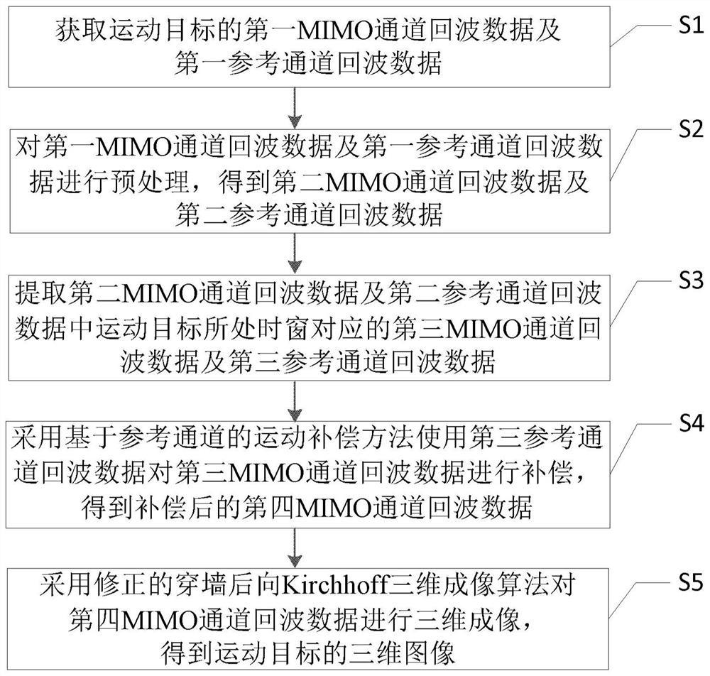
The invention provides a moving target three-dimensional imaging method for an ultra-wideband MIMO through-wall radar. The moving target three-dimensional imaging method comprises the following steps: S1, acquiring first MIMO channel echo data and first reference channel echo data of a moving target; S2, preprocessing the echo data in the S1 to obtain second MIMO channel echo data and second reference channel echo data; s3, extracting third MIMO channel echo data and third reference channel echo data corresponding to a time window where the moving target is located in the second MIMO channel echo data and the second reference channel echo data; s4, compensating the third MIMO channel echo data by using the third reference channel echo data by adopting a motion compensation method based on a reference channel to obtain compensated fourth MIMO channel echo data; and S5, performing three-dimensional imaging on the fourth MIMO channel echo data by adopting a corrected through-wall backward Kirchhoff three-dimensional imaging algorithm to obtain a three-dimensional image of the moving target. The invention further provides a moving target three-dimensional imaging device for the ultra-wideband MIMO through-wall radar.

Description

technical field [0001] The present disclosure relates to the field of three-dimensional imaging of moving targets with MIMO through-wall radars, and in particular to a method and device for three-dimensional imaging of moving targets for ultra-wideband MIMO through-wall radars. Background technique [0002] Ultra-wideband MIMO radar is widely used in the field of through-wall imaging because of its good penetration and ultra-high range resolution. The azimuth resolution of MIMO through-wall radar depends on the aperture of the MIMO array. The larger the aperture, the higher the azimuth resolution. At the same time, the number of required arrays will increase dramatically, which is difficult to realize on the hardware system. [0003] At present, most projects implement MIMO systems in a time-division multiplexing manner through microwave switching, which implements MIMO transceivers with a simple structure and low cost. However, when the system is used for 3D imaging of m...

Claims


Application Information

Patent Timeline
Patent Type & Authority Applications(China)
IPC IPC(8): G01S13/89G01S7/41
CPCG01S13/89G01S7/418Y02A90/10
Inventor 叶盛波潘俊方广有
Owner AEROSPACE INFORMATION RES INST CAS
Learn More