
Circuit breaker wiring method

A wiring method and circuit breaker technology, applied in the direction of protective switch terminals/connections, etc., can solve the problems of large gaps, no protective measures, electric shock hazards, etc., and achieve the effect of simple operation

Inactive Publication Date: 2021-06-11
淄博萃智工业设计咨询有限公司
View PDF1 Cites 0 Cited by
  • Summary
  • Abstract
  • Description
  • Claims
  • Application Information

AI Technical Summary

Problems solved by technology

But it has the following problems: 1. The fixing bolts of the connecting terminal are also kept in communication with the outside world through the jack for inserting the screwdriver, causing electric shock hazards; There is a possibility of water or other metal objects entering the hole where the wire is inserted and causing an electric shock accident
[0004] The patent with the publication number CN106783416A discloses a safety leakage circuit breaker and its use method. The terminal 3 includes a fixed terminal 31 and a U-shaped sliding terminal 32 to clamp the wire, but the wiring hole 14b for inserting the wire Without any protective measures, the gap between the wire and the wiring hole 14b after the wire is inserted has a large potential safety hazard

Method used


Image

  • Circuit breaker wiring method
  • Circuit breaker wiring method
  • Circuit breaker wiring method

Examples


Embodiment Construction

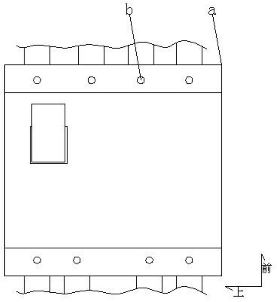
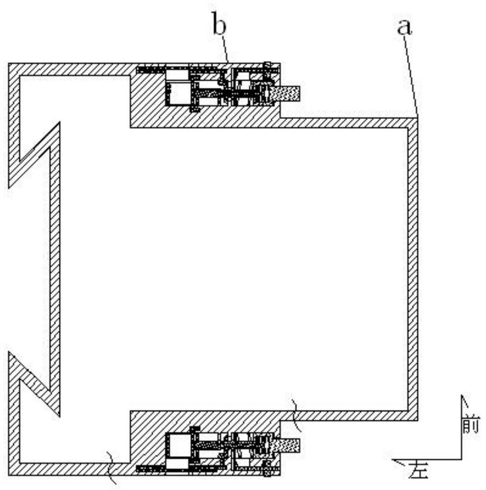
[0079] A safety circuit breaker, comprising a circuit breaker body a and a self-protection terminal b;

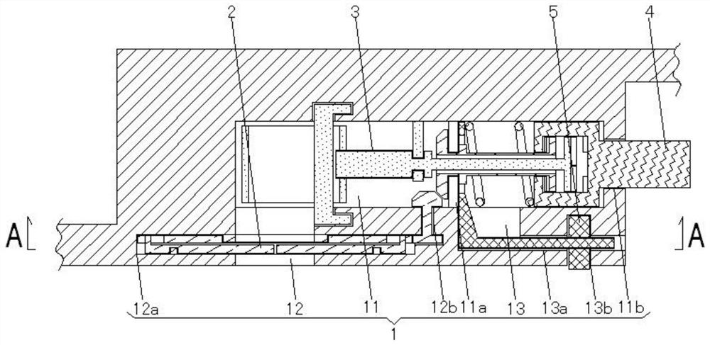
[0080] The self-protection terminal b is symmetrically arranged on the left, right, front and rear sides of the circuit breaker body, and the self-protection terminal b at least includes a terminal chamber 1, an opening and closing device 2, a clamping terminal 3, and an operating device 4;

[0081] The terminal chamber 1 includes:

[0082] The middle chamber 11 is arranged in the middle part of the self-protection terminal along the left and right direction. The middle part of the middle chamber 11 is formed with a middle cavity retaining ring 11a, and the right end of the middle chamber 11 is provided with a right through hole 11b;

[0083] The wiring insertion hole 12 is connected and arranged behind the left half of the middle chamber 11. The central part of the wiring insertion hole 12 is widened and formed with an annular chamber 12a, and the right side of the annular...


PUM


Abstract

The invention discloses a circuit breaker wiring method. A safety circuit breaker is used, and a circuit breaker main body and self-protection wiring terminals are included; the self-protection wiring terminals are symmetrically arranged on the left side, the right side, the front side and the rear side of the circuit breaker main body; and each self-protection wiring terminal at least comprises a terminal cavity, an opening and closing device, a wire clamping terminal and an operation device. The wiring method comprises the following steps: 1, opening and closing an opening and closing device; 2, conducting wire connection; 3, clamping the wire clamping terminals; and 4, adjusting damping.

Description

technical field [0001] The invention relates to the technical field of circuit breakers, in particular to a circuit breaker wiring method. Background technique [0002] Leakage circuit breaker is a switch that can automatically operate when the leakage current in the circuit exceeds a predetermined value, mainly to prevent personal electric shock. Some circuit breakers are also integrated with residual current protection. In the event of leakage, the tripping device operates to cut off the power of the circuit breaker. [0003] When the circuit breaker of the prior art is connected to the electric wire, the insulation sheath of the electric wire is stripped off, and then the conductive metal core is inserted into the terminal for fixing. But it has the following problems: 1. The fixing bolts of the connecting terminal are also kept in communication with the outside world through the jack for inserting the screwdriver, causing electric shock hazards; There is a possibility ...

Claims


Application Information

Patent Timeline
Patent Type & Authority Applications(China)
IPC IPC(8): H01H71/08
CPCH01H71/08
Inventor 孙海波李兴亭
Owner 淄博萃智工业设计咨询有限公司
Learn More