
Frequency selective surface structure, manufacturing method thereof, antenna housing and manufacturing method thereof

A frequency-selective surface and radome technology, which is applied to antennas, antenna parts, and radiation unit covers, can solve the problems of difficult surface structure shaping and unfavorable equipment conformal design, so as to achieve good equipment conformality and improve consistency sexual effect

Pending Publication Date: 2021-06-11
ZHONGTIAN COMM TECH CO LTD
View PDF9 Cites 0 Cited by
  • Summary
  • Abstract
  • Description
  • Claims
  • Application Information

AI Technical Summary

Problems solved by technology

[0004] However, it is difficult to shape the above-mentioned frequency selective surface structure. When the above-mentioned frequency selective surface structure is made into products such as radomes, it is not conducive to conformal design with equipment using products such as radomes.

Method used

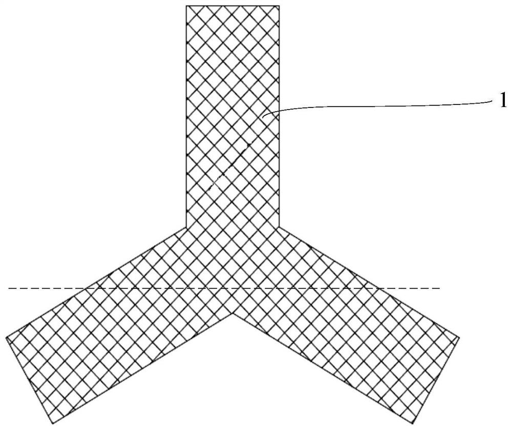
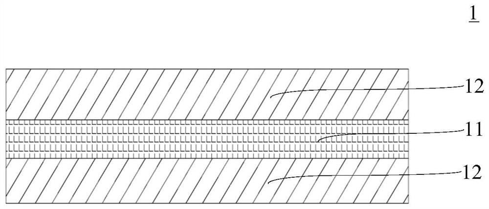

Image

  • Frequency selective surface structure, manufacturing method thereof, antenna housing and manufacturing method thereof
  • Frequency selective surface structure, manufacturing method thereof, antenna housing and manufacturing method thereof
  • Frequency selective surface structure, manufacturing method thereof, antenna housing and manufacturing method thereof

Examples


Embodiment 1

[0083] Such as Figure 7-Figure 11 As shown, the frequency selective surface structure further includes a substrate 2, the substrate 2 includes a substrate skeleton 21, and the substrate skeleton 21 and the passive resonant skeleton 11 are independently woven and formed, and the substrate skeleton 21 is woven by a non-conductive first silk thread, passive The resonant frame 11 is braided by conductive second wires. Since the substrate frame 21 is woven by the first thread, the substrate frame 21 can be woven into a shape such as a sheet or a tube, or can be woven into a shape of a product such as a radome.

[0084] Compared with the integral braiding of the substrate skeleton 21 and the passive resonant skeleton 11, the substrate skeleton 21 and the passive resonant skeleton 11 are independently braided and formed to obtain a mutually independent substrate 2 and passive resonant diaphragm 1, and only need to adjust the passive resonant membrane The position of the sheet 1 on ...

Embodiment 2

[0093] Such as Figure 12-Figure 23 As shown, the frequency selective surface structure also includes a substrate 2, the substrate 2 includes a substrate skeleton 21, and the substrate skeleton 21 is integrally woven with a plurality of passive resonant skeletons 11 to form a passive resonant hybrid skeleton 7, and the plurality of passive resonant skeletons 11 Periodically arranged in the substrate skeleton 21 . Since the passive resonant hybrid framework 7 is woven from silk threads, the passive resonant hybrid framework 7 can be woven into shapes such as sheets and tubes, and can also be woven into shapes of products such as radome. In addition, since the substrate skeleton 21 is integrally braided with the multiple passive resonant skeletons 11 , the passive resonant skeleton 11 and the substrate skeleton 21 are not easily separated, which can improve the structural stability of the frequency selective surface structure.

[0094] It can be understood that, since the subst...


PUM


Abstract

The invention provides a frequency selective surface structure and a manufacturing method thereof, and an antenna housing and a manufacturing method thereof, relates to the technical field of antennas, and is used for solving the technical problem that the shaping difficulty of the frequency selective surface structure is relatively high. The frequency selective surface structure comprises a plurality of passive resonant diaphragms. Each passive resonant diaphragm comprises a first resin layer and a passive resonant skeleton with a preset shape, the passive resonant skeleton is coated with the first resin layer, and the passive resonant skeleton is formed by weaving non-conductive first silk threads or conductive second silk threads. The frequency selective surface structure provided by the invention is used for filtering.

Description

technical field [0001] The invention relates to the technical field of antennas, in particular to a frequency selective surface structure and a manufacturing method thereof, a radome and a manufacturing method thereof. Background technique [0002] Frequency Selective Surface (FSS) is a single-layer or multi-layer quasi-planar structure composed of multiple passive resonant units arranged in two-dimensional periodicity on the dielectric layer. It is essentially a spatial filter. The interaction with electromagnetic waves shows obvious band-pass or band-stop filtering characteristics, and is widely used in antenna filtering, radar stealth and other fields. [0003] A common frequency selective surface structure includes a dielectric substrate and passive resonant diaphragms periodically arranged on the dielectric substrate, and each passive resonant diaphragm is a passive resonant unit. When making the frequency selective surface structure, it is necessary to cover the metal...

Claims


Application Information

Patent Timeline
IPC IPC(8): H01Q15/00H01Q1/42
CPCH01Q15/0013H01Q1/427
Inventor 谷宝生符小东揭水平王学仁徐翠蒋鹏飞吴海龙靳志尧汤曹磊
Owner ZHONGTIAN COMM TECH CO LTD
Learn More