
Rotating mechanism

A technology of rotating mechanism and rotor, applied in the field of power engineering, can solve the problems of large occupied volume and expensive reducer

Pending Publication Date: 2021-06-11
王伟
View PDF0 Cites 0 Cited by
  • Summary
  • Abstract
  • Description
  • Claims
  • Application Information

AI Technical Summary

Problems solved by technology

[0003] The purpose of the present invention is to provide a rotating mechanism for the problem that the current reducer is expensive and takes up a large volume

Method used


Image

  • Rotating mechanism
  • Rotating mechanism
  • Rotating mechanism

Examples


Embodiment Construction

[0020] The present invention will be further described in detail below in conjunction with test examples and specific embodiments. However, it should not be understood that the scope of the above subject matter of the present invention is limited to the following embodiments, and all technologies realized based on the content of the present invention belong to the scope of the present invention.

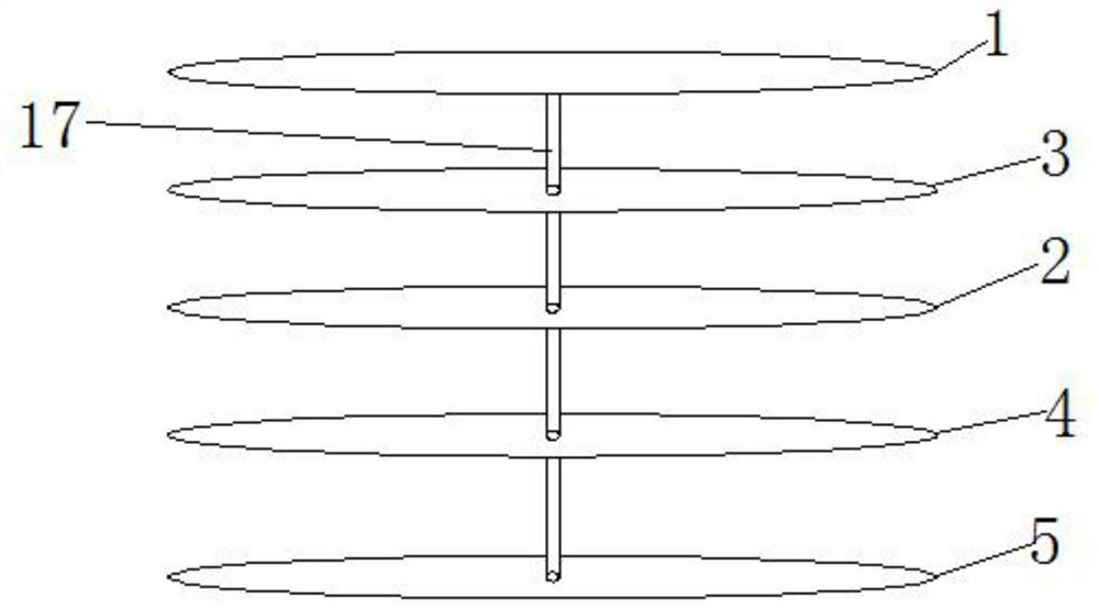
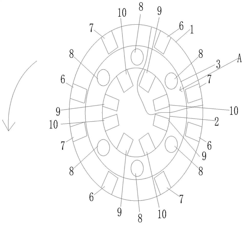
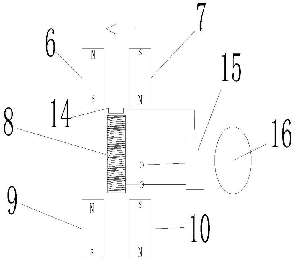
[0021] This embodiment proposes a rotating mechanism, such as figure 1 As shown, it includes the first rotor 1, the second rotor 2, the third rotor 5, the first stator 3 and the second stator 4, which are arranged and connected at intervals from top to bottom, and the five are connected by a shaft 17, and the first rotor 1. The second rotor 2 and the third rotor 5 are fixed on the rotating shaft 17, and the rotation of one of the three can drive the other two to rotate. The first stator 3 and the second stator 4 are connected to the rotating shaft 17 through bearings, so that When t...


PUM


Abstract

A rotating mechanism disclosed by the present invention comprises a first rotor, a first stator and a circuit, the first stator is provided with a first electromagnet, and the first rotor is provided with a first magnet and a second magnet which are arranged at an interval. The magnetic pole of the end face, facing the first electromagnet, of the first magnet is opposite to the magnetic pole of the end face, facing the first electromagnet, of the second magnet, the circuit comprises a power source, a PLC and a coil of the first electromagnet, the power source, the PLC and the coil of the first electromagnet are electrically connected in sequence and form a loop, and the PLC is connected with a bipolar latch type Hall effect sensor. The direction of the coil input on the electromagnet is continuously changed through the bipolar latch type Hall effect sensor, so that the magnetic poles on the two end faces of the electromagnet are continuously changed, a plurality of permanent magnets arranged on the rotor are attracted and repelled, the rotor is driven to rotate, a speed reducer is not needed in the aspect of controlling the rotating speed of the rotor, and the purpose of speed reduction can be achieved only by adjusting the magnetic energy of the permanent magnets by adjusting the types of the permanent magnets.

Description

technical field [0001] The invention relates to the field of power engineering, in particular to a rotating mechanism. Background technique [0002] In the existing rotating mechanism, the speed is generally reduced by connecting the prime mover with the reducer. However, the reducer is expensive, and the commonly used reducer uses a gear with a small number of teeth on the input shaft to mesh with a gear on the output shaft. Large gears are used to achieve the purpose of deceleration, so the volume is relatively large and requires a large space. Contents of the invention [0003] The object of the present invention is to provide a rotating mechanism for the problem that the current reducer is expensive and takes up a large volume. [0004] In order to realize the above-mentioned purpose of the invention, the present invention provides the following technical solutions: [0005] A rotating mechanism, the rotating mechanism includes a first rotor, a first stator, and a ci...

Claims


Application Information

Patent Timeline
Patent Type & Authority Applications(China)
IPC IPC(8): H02K16/00H02K1/27H02J7/14
CPCH02J7/14H02K1/2793H02K16/00
Inventor 王伟
Owner 王伟
Learn More