Area-variable storage type iron stand bed
A variable, iron frame technology, applied in the field of iron frame beds, can solve the problems of large space occupation, inability to allow many people to sleep together, and affect people's walking, etc., to achieve the effect of increasing the area
- Summary
- Abstract
- Description
- Claims
- Application Information
AI Technical Summary
Problems solved by technology
Method used
Image
Examples
Embodiment 1
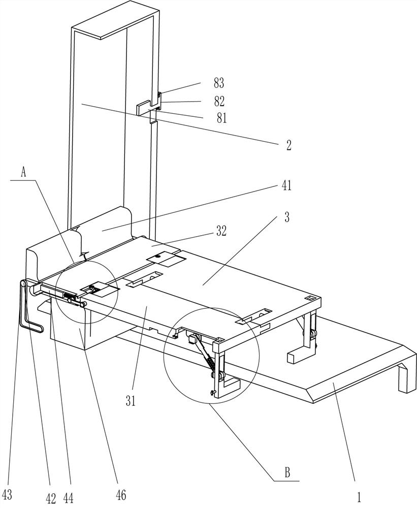
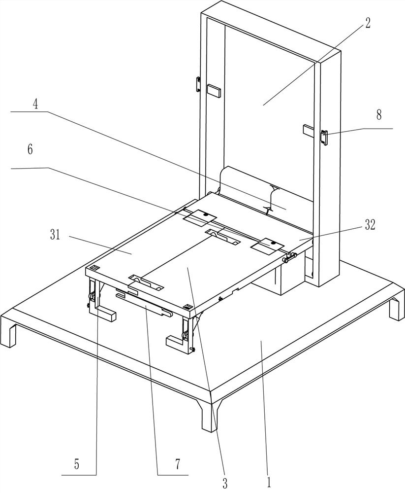
[0026] A retractable iron frame bed with variable area, such as Figure 1-Figure 4 As shown, it includes a base 1, a support cabinet 2, a first bed board 3, a second bed board 31, a rotating board 32, a storage mechanism 4, and a support mechanism 5. There is a rotating plate 32 connected to the lower part of the inner left and right sides. The front side of the rotating plate 32 is slidingly provided with a first bed board 3 and a second bed board 31. The first bed board 3 and the second bed board 31 cooperate with each other. A support mechanism 5 is provided on the bottom front side of the bed board 3 and the second bed board 31 , and a storage mechanism 4 is provided between the rear side of the rotating plate 32 and the support cabinet 2 and the top rear side of the base 1 .
[0027] Storage mechanism 4 comprises back cushion 41, guide bar 42, L-shaped slide rail 43, telescopic guide rail 44, guide spring 45 and support cushion 46, and the left and right side both sides b...
Embodiment 2
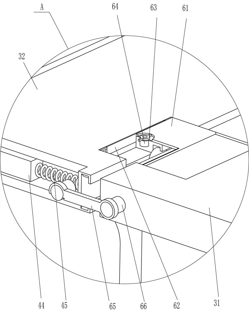
[0033] On the basis of Example 1, such as figure 1 , figure 2 , image 3 , Figure 5 and Image 6 As shown, a positioning mechanism 6 is also included, and the positioning mechanism 6 includes a positioning plate 61, a hinged connecting plate 62, a locking knob 63, a locking seat 64, a rubber locking bar 65 and a fixed column 66, and the left part of the second bed board 31 top rear side All rotatably connected to the right part of the rear side of the top of the first bed board 3 is a positioning plate 61, and the rear end of the locating plate 61 is rotatably connected with a hinged connecting plate 62. The hinged connecting plate 62 cooperates with the inside of the rotating plate 32, and the top of the rotating plate 32 The left and right sides of the front side are symmetrically fixedly connected with a locking seat 64, and the top of the locking seat 64 is rotatably connected with a locking knob 63. The locking knob 63 cooperates with the hole of the positioning plat...
Embodiment 3
[0038] On the basis of embodiment 1 and embodiment 2, such as figure 1 , figure 2 , Figure 5 and Image 6 As shown, a locking mechanism 8 is also included, and the locking mechanism 8 includes a locking plate 81, a force-bearing block 82 and a positioning spring 83, and the upper and lower front parts of the left and right sides of the support cabinet 2 are slidably connected with the locking plate 81 to lock The plate 81 cooperates with the first bed board 3 and the second bed board 31, and the outer end of the locking board 81 is fixedly connected with a load-bearing block 82, and the upper and lower sides of the inner side of the left and right sides of the load-bearing block 82 and the top of the outer, left, and right sides of the support cabinet 2 A positioning spring 83 is connected.
[0039] Also include supporting auxiliary mechanism 9, supporting auxiliary mechanism 9 includes supporting rod 91, rubber foot seat 92 and supporting spring 93, all are hinged with s...
PUM
 Abstract
Description
Claims
Application Information
 - R&D
- Intellectual Property
- Life Sciences
- Materials
- Tech Scout
- Unparalleled Data Quality
- Higher Quality Content
- 60% Fewer Hallucinations
Browse by: Latest US Patents, China's latest patents, Technical Efficacy Thesaurus, Application Domain, Technology Topic, Popular Technical Reports.
© 2025 PatSnap. All rights reserved.Legal|Privacy policy|Modern Slavery Act Transparency Statement|Sitemap|About US| Contact US: help@patsnap.com


