Intelligent pipe bending equipment
A pipe, intelligent technology, applied in metal processing equipment, storage devices, feeding devices, etc., to save labor and time costs
- Summary
- Abstract
- Description
- Claims
- Application Information
AI Technical Summary
Problems solved by technology
Method used
Image
Examples
specific Embodiment approach 1
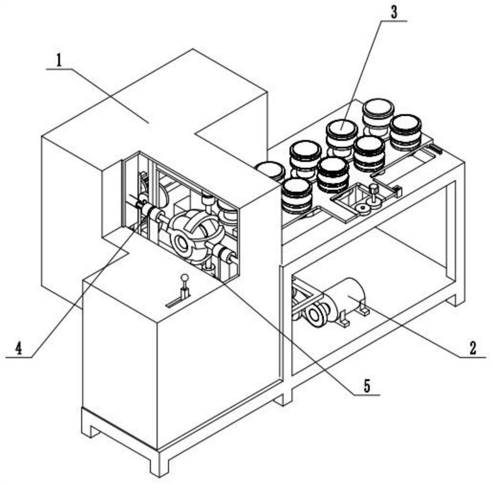
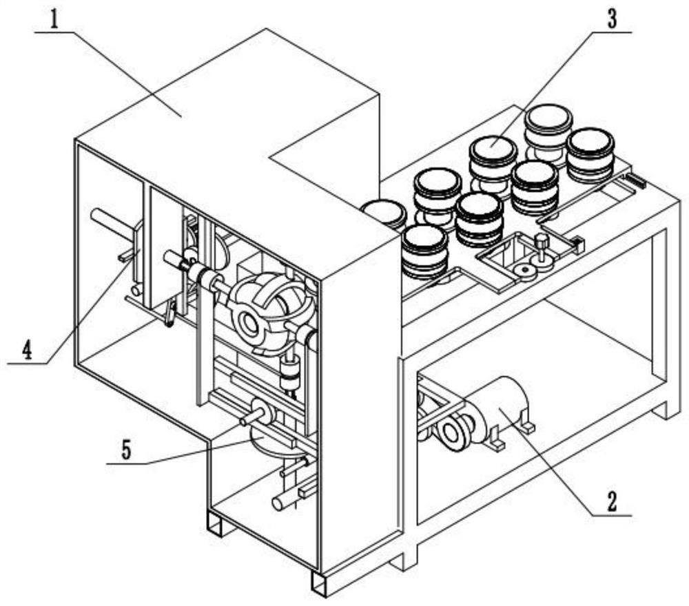
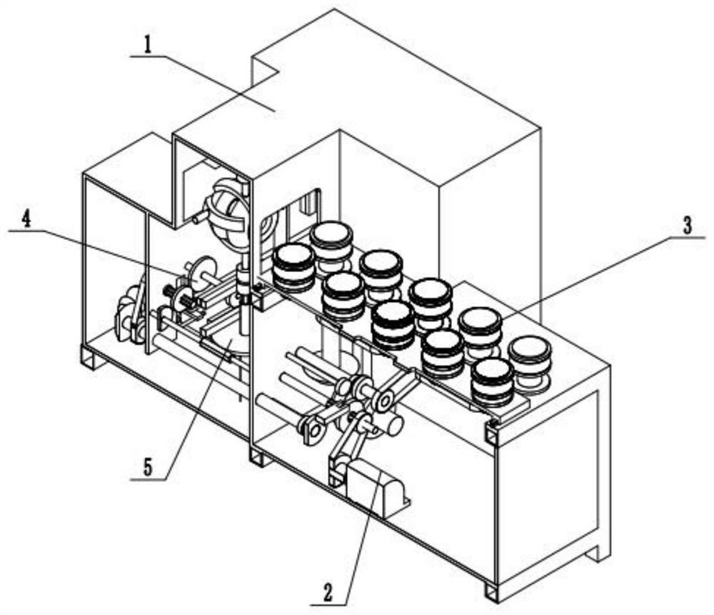
[0029] Combine below figure 1 , 2 , 3, 4, 5, 6, 7, 8, 9, 10, 11, 12, 13 In order to solve the above technical problems, an intelligent pipe bending equipment includes a frame 1, a transmission distribution device 2, and a material feeding device 3. Horizontal bending device 4. Vertical bending device 5. Other devices are installed through the frame, the main power of the transmission distribution device and the distribution of various parts of the action, and the material feeding device conveys, limits and clamps the straight pipe , The horizontal bending device realizes the bending of the pipe in the horizontal direction, and the vertical bending device realizes the bending of the pipe in the vertical direction, so that the straight pipe can be bent at multiple angles during the bending process and saves the cost of loading and unloading Manpower and time cost function, characterized in that: the transmission distribution device is installed and fixed inside the frame, the m...
specific Embodiment approach 2
[0031] Combine below figure 1 , 2 , 3, 4, 5, 6, 7, 8, 9, 10, 11, 12, 13 illustrate this embodiment, and this embodiment will further describe Embodiment 1. Frame main body 1-2, bearing seat mounting hole 1-3, rack door 1-4, discharge port 1-5, material receiving platform 1-6, spline clamping block 1-7, rack slide rail 1- 8. Limit bar 1-9, limit pin 1-10, outer cover 1-1 is installed and fixed on the frame main body 1-2, bearing mounting hole 1-3 is arranged on the frame main body 1-2, and the frame door 1-4 is hinged on the frame main body 1-2 through a hinge, the discharge port 1-5 is set on the outer cover 1-1, the material receiving platform 1-6 is installed and fixed on the outer cover 1-1, and the spline clamping block 1 -7 is installed and fixed inside the outer cover 1-1, the rack slide rail 1-8 is installed and fixed inside the outer cover 1-1, the limit bar 1-9 is installed and fixed inside the outer cover 1-1, and the limit pin 1-10 is installed and fixed Inside t...
specific Embodiment approach 3
[0033] Combine below figure 1 , 2 , 3, 4, 5, 6, 7, 8, 9, 10, 11, 12, 13 illustrate this embodiment, and this embodiment will further describe Embodiment 1. The transmission distribution device 2 includes a motor 2-1, Motor output pulley 2-2, motor protection belt 2-3, input pulley 2-4, feed transmission shaft 2-5, feed input gear 2-6, feed driving helical gear 2-7, vertical folding Bent transmission shaft 2-8, vertical transmission duplex gear 2-9, control handle 2-10, handle rocker 2-11, handle limit pin 2-12, handle transfer pin 2-13, shift fork lever 2- 14. Distribution spline shaft 2-15, distribution slip gear 2-16, direction changing gear shaft one 2-17, direction changing gear one 2-18, horizontal transmission duplex gear 2-19, horizontal transmission pulley 2-20 , horizontal transmission shaft 2-21, sliding gear 2-22, pull the control handle 2-10, and the control handle 2-10 rotates around the handle limit pin 2-12 so that the fork lever 2-14 moves the sliding gear 2...
PUM
 Abstract
Description
Claims
Application Information
 - R&D
- Intellectual Property
- Life Sciences
- Materials
- Tech Scout
- Unparalleled Data Quality
- Higher Quality Content
- 60% Fewer Hallucinations
Browse by: Latest US Patents, China's latest patents, Technical Efficacy Thesaurus, Application Domain, Technology Topic, Popular Technical Reports.
© 2025 PatSnap. All rights reserved.Legal|Privacy policy|Modern Slavery Act Transparency Statement|Sitemap|About US| Contact US: help@patsnap.com


