Plate stamping system and machining method thereof

A sheet metal and stamping die technology, applied in the field of door panel processing equipment, can solve problems such as inability to stamp equipment processing operations, reduce equipment processing efficiency, affect work efficiency, etc. Effect

Inactive Publication Date: 2021-06-15
中国机械总院集团江苏分院有限公司
View PDF21 Cites 0 Cited by
  • Summary
  • Abstract
  • Description
  • Claims
  • Application Information

AI Technical Summary

Problems solved by technology

[0004] The purpose of the present invention is to provide a plate stamping system and its processing method, which aims to improve the existing door panel processing equipment with simple structure. After the stamping equipment is used for processing, it is often necessary to carry out pick-and-place operations, wait for cooling and place it A series of operations such as stamping equipment cannot be processed quickly, which will reduce the processing efficiency of the equipment. At the same time, the traditional door panel processing equipment does not have a corresponding placement mechanism during use, requiring multiple people to cooperate. Problems that greatly affect work efficiency

Method used


Image

  • Plate stamping system and machining method thereof
  • Plate stamping system and machining method thereof
  • Plate stamping system and machining method thereof

Examples


Embodiment 1

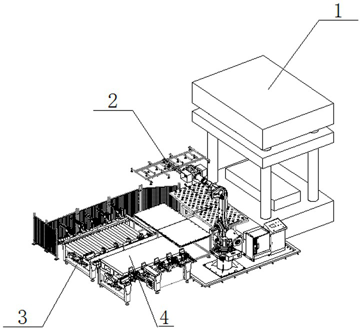
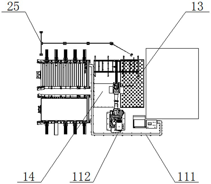
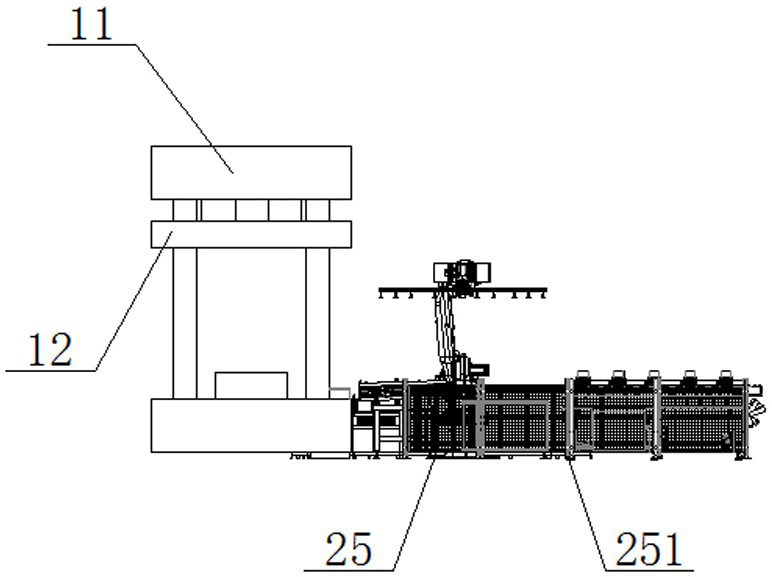
[0046] refer to figure 1 , figure 2 and image 3 As shown, the plate stamping system of this embodiment includes a feeding mechanism 4, a transfer mechanism 2, a stamping die set 1 and a blanking mechanism 3, the stamping die set 1 includes a press 11 and a moving die 12, and the moving die 12 is formed by the press 11 is driven for stamping, the transfer mechanism 2 is set on the side of the stamping die set 1, the unloading mechanism 3 is set on the side of the transfer mechanism 2, and the side of the press 11 is also equipped with a centering die set and a transfer platform 14, and the transfer platform 14 is set On the side of the centering module, the transfer mechanism 2 transfers the door panels on the feeding mechanism 4 to the centering module for centering and then transfers to the stamping module 1. When the unloading backlog, the transfer mechanism 2 transfers the stamped plates Transferring to the transfer platform 14 for temporary storage solves the problem t...

Embodiment 2

[0051] The plate stamping system of this embodiment is basically the same as that of Embodiment 1, the difference is that the centering module is an inclined frame type centering platform 15, the details are as follows:

[0052] Such as Figure 17 and 18 As shown, the inclined frame type centering platform 15 of the present embodiment includes a positioning platform 151 and an inclined frame group 152. The inclined frame group 152 is installed on the lower end surface of the positioning platform 151, and the inclined frame group 152 is fixedly connected with the positioning platform 151. The frame group 152 comprises a square frame 153, a high pole 154, a middle pole 155 and a low pole 156. The high pole 154 and the low pole 156 are respectively arranged on the opposite corners of the square frame 153, and the middle pole 155 is installed on the other two sides of the square frame 153. On the diagonal, and the high pole 154, the middle pole 155 and the low pole 156 are all ve...


PUM


Abstract

The invention discloses a plate stamping system comprising a feeding mechanism, a transfer mechanism, a stamping module and a discharging mechanism, wherein the stamping module comprises a press machine and a movable die; the movable die is driven by the press machine for stamping, and the transfer mechanism is arranged on the side face of the stamping module; the discharging mechanism is arranged on the side face of the transfer mechanism; a centering module and a transfer platform are further installed on the side face of the press machine, and the transfer platform is arranged on the side face of the centering module; it is guaranteed that a user can stably process stamping materials through the stamping module in use, and therefore stable molding of a door panel is achieved; After completion of molding, the user can stably control the transfer mechanism to take down a formed product from the press machine in real time, the user can stably place the product on the ground through a locating plate during actual operation of the transfer mechanism, and the locating plate is fixedly connected with the ground by bolts.

Description

technical field [0001] The invention relates to the technical field of door panel processing equipment, in particular to a panel stamping system and a processing method thereof. Background technique [0002] The mold used for stamping is called a stamping die. The stamping die is a special tool for batch processing materials into the required punching parts. The stamping die is very important in stamping. The stamping door panel is obtained by stamping the stamping material with a stamping die. Through batch stamping The production of stamped door panels that meet the requirements requires the cooperation of stamping dies, stamping processes, stamping equipment and stamping materials to make qualified stamping parts. [0003] The inventors of the present application found that the existing door panel processing equipment has a simple structure. After the stamping equipment is used for processing, it is often necessary to perform a series of operations such as pick-and-place ...

Claims


Application Information

Patent Timeline
Patent Type & Authority Applications(China)
IPC IPC(8): B21D43/24B21D43/22B21D43/00B21D43/18
CPCB21D43/003B21D43/18B21D43/22B21D43/24
Inventor 周永松张振陈雷鸣成志远邹海峰杨皓清李杰
Owner 中国机械总院集团江苏分院有限公司
Why Eureka
Try Eureka