Power transmission line tower structure for goaf

A technology for transmission lines and goafs, applied in infrastructure engineering, towers, building types, etc., can solve problems such as difficulty in implementing deviation correction, foundation settlement and deformation, and unstable foundations in goafs.

Active Publication Date: 2021-06-15
王克东
View PDF8 Cites 0 Cited by
  • Summary
  • Abstract
  • Description
  • Claims
  • Application Information

AI Technical Summary

Problems solved by technology

Based on this, the erection of transmission lines is generally not carried out in goaf areas, but due to the limitation of transmission line channels, some transmission lines must be erected in goaf areas
Due to the geological reasons of the goaf, the foundation of the goaf is unstable and prone to foundation settlement and deformation. However, the existing general tower foundation structure cannot realize deviation correction adjustment or is difficult to implement during deviation correction. Therefore, in-depth research and improvement are urgently needed

Method used


Image

  • Power transmission line tower structure for goaf
  • Power transmission line tower structure for goaf
  • Power transmission line tower structure for goaf

Examples


Embodiment 1

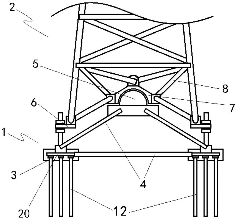
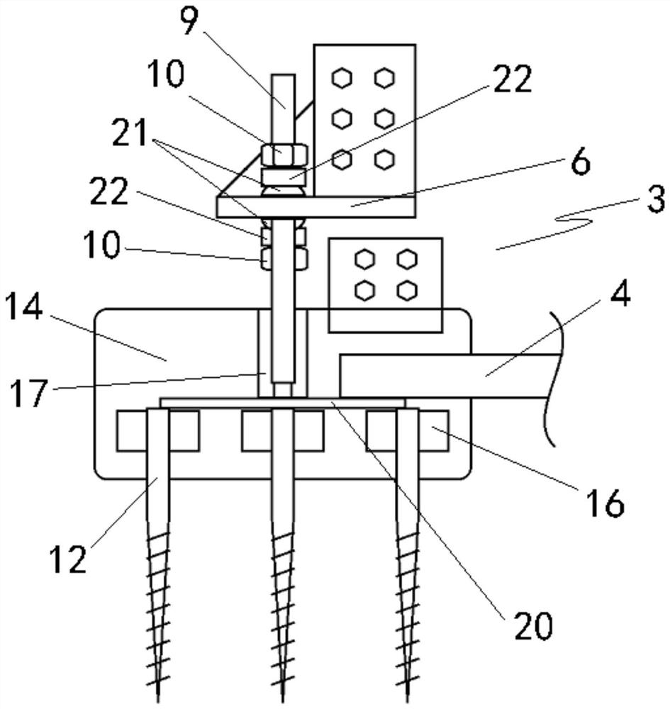
[0017] according to figure 1 , figure 2 , image 3 As shown, a power transmission line tower structure for gobs includes a tower base 1 and a tower body 2 connected to the tower base 1, and the tower base 1 includes a plurality of bases arranged in a rectangular array 3, and the ball joint 5 fixedly arranged above the tower foundation 1 through the bottom bracket 4; the bottom of the tower body 2 is provided with an adjusting foot plate 6 corresponding to each of the bases 3, and the center of the bottom of the tower body 2 The upper bracket 8 is fixed with the ball bowl 7 that cooperates with the ball joint 5; each of the abutments 3 is respectively provided with an adjustment screw 9 extending vertically upward, and each of the adjustment feet 6 passes through the adjustment hole Cooperate with the adjusting stud 9 and fix it by double nuts 10.

[0018] In the above setting, the tower base 1 bears the main weight of the tower body 2 through the cooperation of the ball jo...

Embodiment 2

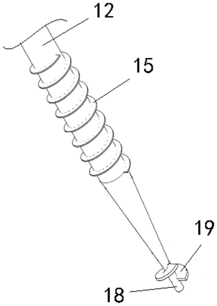
[0020] Each of the abutments 3 is composed of a foundation pile 12 and a concrete pouring body 14; the foundation pile 12 is a pointed cone structure with a plurality of tips inserted into the ground, and the conical surfaces of each of the foundation piles 12 are concentric. A first helical blade 15 is provided, the outer diameter of the first helical blade 15 is equal to the outer diameter of the large end of the foundation pile 12, and the large ends of each of the foundation piles 12 are also radially connected with a plurality of fins 16 ; the concrete pouring body 14 is a solid structure solidified and connected to the top of each foundation pile 12 , and the adjusting stud 9 is fixedly arranged on the top of the concrete pouring body 14 . The tip of the foundation pile 12 is provided with an axially extending positioning shaft 18; the outer wall of the positioning shaft 18 is provided with a second helical blade 19, and the pitch of the second helical blade 19 is greater...

Embodiment 3

[0023] It also includes a connecting screw sleeve 17, which is prefabricated longitudinally in the center of the concrete pouring body 14, and the top end of the connecting screw sleeve 17 is flush with the installation surface of the concrete pouring body 14, and the adjusting stud The bottom of 9 is threadedly engaged with the connecting screw sleeve 17. In this setting, the adjusting screw 9 cooperates with the connecting screw sleeve 17, which not only ensures the reliability of the connection between the adjusting screw sleeve 17 and the concrete pouring body 14, but also facilitates maintenance and updating of the adjusting screw 9 later.


PUM


Abstract

The invention relates to the technical field of power transmission, in particular to a power transmission line tower structure for a goaf. The power transmission line tower structure comprises a tower footing and a tower body, wherein the tower body is connected to the tower footing, and the tower footing comprises a plurality of base tables which are arranged in a rectangular array and a ball joint which is fixedly arranged above the tower footing through a bottom bracket; adjusting foot plates which correspond to the base tables are arranged at the bottom of the tower body, and a ball bowl which is matched with the ball joint is fixedly arranged in the center of the bottom of the tower body through an upper bracket; and adjusting studs which vertically extend upwards are respectively arranged on the base tables, and the adjusting foot plates are matched with the adjusting studs through penetrating adjusting holes and are fixed through double nuts. When a foundation has settlement change, the inclination of the tower body can be rectified through the matching of the adjusting studs and the adjusting foot plates.

Description

technical field [0001] The invention relates to the technical field of power transmission towers, in particular to a power transmission line tower structure used in goafs. Background technique [0002] Goaf refers to the hollow area left after the mining of underground minerals. According to the time when the minerals were mined, it can be divided into old goaf and current goaf. After the ore body is taken, three zones are formed upward from the roof layer, namely: the falling zone, the fissure zone and the bending zone, the surface subsides, and produces continuous and discontinuous deformation. After the goaf occurs, the overlying rock formation will lose its support, and the original balance condition will be destroyed, causing the overlying rock house to move and deform until it collapses; at the same time, after the goaf, the underground rock mass structure will be destroyed, causing the ground Subsidence and displacement cause damage to existing structures, roads, rai...

Claims


Application Information

Patent Timeline
IPC IPC(8): E02D27/32E02D27/42E02D27/14E02D35/00E04H12/22
CPCE02D27/32E02D27/42E02D27/14E02D35/00E04H12/2253E04H12/2292E02D2300/002E02D2600/20Y02E10/728
Inventor 王克东张启峰岳英民黄锋朱多林李玄哲
Owner 王克东
Why Eureka
Try Eureka