Vertical recovery method for carrier rocket base stage by using vernier engines

A technology for launch vehicles and recovery methods, which is applied to machines/engines, rocket engine devices, mechanical equipment, etc., can solve problems such as difficulty, complex design, and inability to guarantee reliability, achieve wide application, avoid deep throttling, and achieve convenient effects

Active Publication Date: 2021-06-15
NO 63921 UNIT OF PLA
View PDF18 Cites 8 Cited by
  • Summary
  • Abstract
  • Description
  • Claims
  • Application Information

AI Technical Summary

Problems solved by technology

Under the current technical conditions, deep throttling and multiple start-up modification of high-thrust rocket engines have the disadvantages of complex design, great difficulty, and unguaranteed reliability. Adaptive adaptation to meet power requirements in reusable launch vehicles

Method used


Image

  • Vertical recovery method for carrier rocket base stage by using vernier engines
  • Vertical recovery method for carrier rocket base stage by using vernier engines
  • Vertical recovery method for carrier rocket base stage by using vernier engines

Examples


Embodiment 1

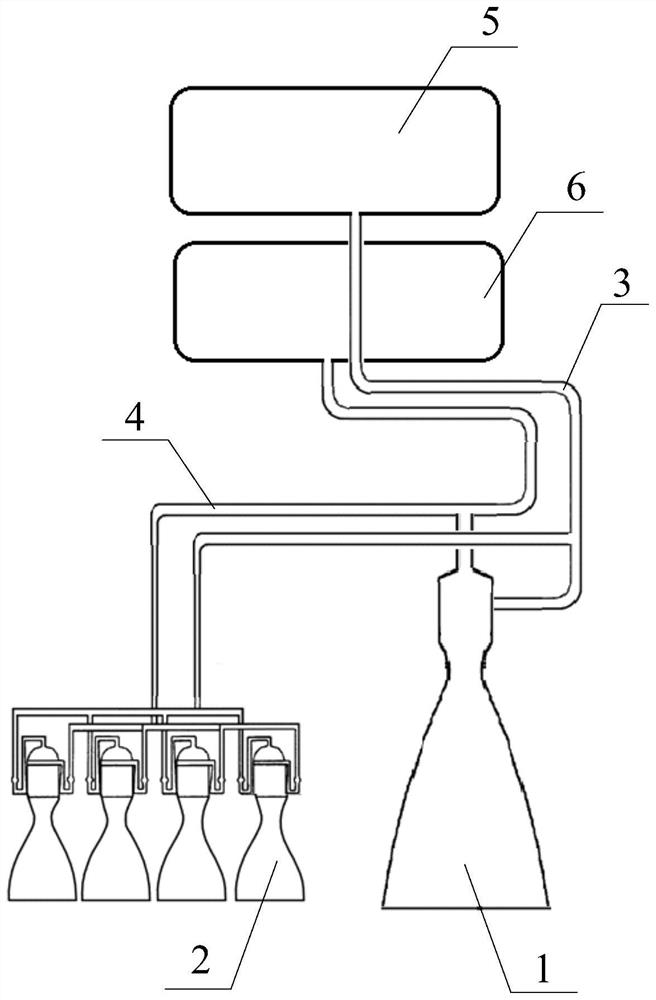
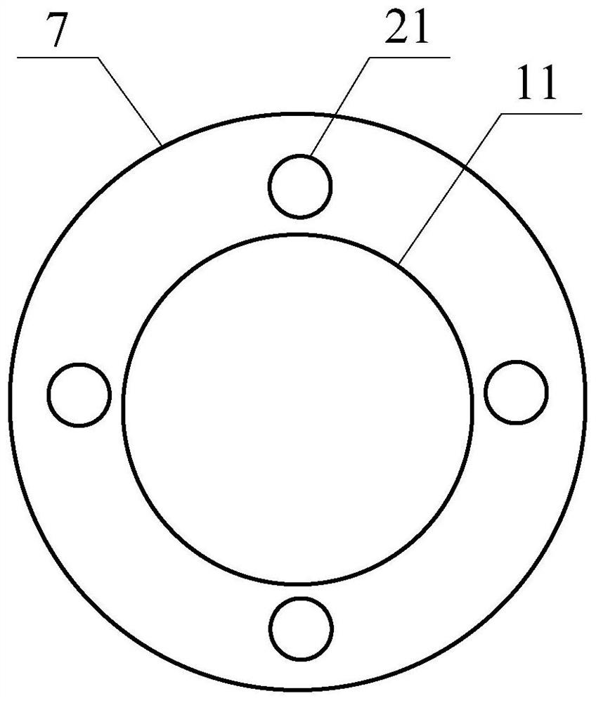
[0047] The basic stage of the launch vehicle is equipped with a main engine 1 and four swimming engines 2, in which liquid oxygen is used as the oxidant, and kerosene is used as the combustion agent; the main engine 1 is equipped with a main engine nozzle 11, and the thrust at sea level is 300 tons. Oxygen-enriched supplementary combustion cycle is adopted; each traveling engine 2 is equipped with a traveling engine nozzle 21, and the sea level thrust of each traveling engine 2 is 10 tons, and the diameter of the basic stage of the launch vehicle can be 3.35 meters. The structural mass (including the engine) is 20 tons; the layout of the main engine nozzle 11 and the swimming engine nozzle 21 is as follows: image 3 structure shown.

Embodiment 2

[0049] The basic stage of the launch vehicle is equipped with a main engine 1 and four swimming engines 2, in which liquid oxygen is used as the oxidant, and liquid hydrogen is used as the combustion agent; the main engine 1 is equipped with a main engine nozzle 11, and the thrust at sea level is 300 tons , using a supplementary combustion cycle; each traveling engine 2 is equipped with a traveling engine nozzle 21, the sea level thrust of each traveling engine 2 is 15 tons, the diameter of the basic stage of the launch vehicle can be 5 meters, and the structural quality of the basic stage is (including the engine) is 30 tons; the layout of the main engine nozzle 11 and the swimming engine nozzle 21 is as follows: image 3 structure shown.

Embodiment 3

[0051] The basic stage of the launch vehicle is equipped with a main engine 1 and six swimming engines 2, in which liquid oxygen is used as the oxidant, and kerosene is used as the combustion agent; the main engine 1 is equipped with a main engine nozzle 11, and the thrust at sea level is 300 tons. Oxygen-enriched supplementary combustion cycle is adopted; each traveling engine 2 is equipped with a traveling engine nozzle 21, the sea level thrust of each traveling engine 2 is 8 tons, the diameter of the base stage of the launch vehicle is 3.8 meters, and the structural quality of the base stage is (including the engine) is 25 tons; the layout of the main engine nozzle 11 and the swimming engine nozzle 21 is as follows: Figure 4 structure shown.


PUM


Abstract

The invention discloses a vertical recovery method for a carrier rocket base stage by using vernier engines. The vertical recovery method comprises the steps that the carrier rocket base stage is provided and powered by a combined engine; in the rising stage of a carrier rocket, a main engine provides main flight power, and the vernier engines provide posture control power; after the carrier rocket base stage is separated, the main engine is shut down and descends after flying to the highest point, and the vernier engines provide deceleration power; when the carrier rocket base stage enters a dense atmosphere area, the vernier engines are shut down; and when the carrier rocket base stage descends to the low altitude, the vernier engines are started to provide landing deceleration power. According to the vertical recovery method, the carrier rocket base stage can be vertically recovered, so that repeated use of the carrier rocket base stage is realized, and the utilization efficiency is improved.

Description

technical field [0001] The invention belongs to the technical field of vehicles, and in particular relates to a method for vertically recovering the base stage of a carrier rocket using a swimming engine. Background technique [0002] The reuse of launch vehicles is an effective way to achieve low-cost access to space. Through sub-level controllable recovery, inspection and maintenance, and reuse to reduce launch costs and greatly improve the economy of launch vehicles, it has become an advanced direction for the development of launch vehicle technology. Therefore, the reuse of launch vehicles is the first choice for newly developed launch vehicles to carry out normal space launches. [0003] The vertical recovery technology of the basic stage of international mainstream launch vehicles adopts the parallel connection scheme of multiple identical engines. One engine is located in the center of the rocket body, and the other engines are arranged symmetrically around the center...

Claims


Application Information

Patent Timeline
IPC IPC(8): F02K9/42F02K9/44F02K9/80F02K9/97
CPCF02K9/42F02K9/44F02K9/80F02K9/97
Inventor 周城宏程洪玮刘阳雍子豪谷建光刘鹰朱雄峰王一杉韩秋龙谭云涛
Owner NO 63921 UNIT OF PLA
Why Eureka
Try Eureka