Self-cleaning positive pressure ventilation system of industrial factory building

A technology for positive pressure ventilation and industrial plants, applied in ventilation systems, air conditioning systems, space heating and ventilation, etc., can solve problems such as dust entering the interior of the plant, poor air quality, etc., to facilitate disassembly, improve air temperature, and reduce maintenance cost effect

Inactive Publication Date: 2021-06-15
DESIGN INST NO 9 MINISTRY OF MECHINE BUILDING
View PDF7 Cites 1 Cited by
  • Summary
  • Abstract
  • Description
  • Claims
  • Application Information

AI Technical Summary

Problems solved by technology

[0005] Aiming at the deficiencies of the prior art, the present invention provides a self-cleaning positive-pressure ventilation system for industrial plants, which has the advantages of positive-pressure ventilation and dust filtering, and solves the problem that the external dust will be blown from the doors and windows during the normal negative-pressure ventilation. Entering the interior of the factory building, it is easy to cause the defect of poor air quality in the factory building

Method used


Image

  • Self-cleaning positive pressure ventilation system of industrial factory building
  • Self-cleaning positive pressure ventilation system of industrial factory building
  • Self-cleaning positive pressure ventilation system of industrial factory building

Examples


Embodiment Construction

[0027] The following will clearly and completely describe the technical solutions in the embodiments of the present invention with reference to the accompanying drawings in the embodiments of the present invention. Obviously, the described embodiments are only some, not all, embodiments of the present invention. Based on the embodiments of the present invention, all other embodiments obtained by persons of ordinary skill in the art without making creative efforts belong to the protection scope of the present invention.

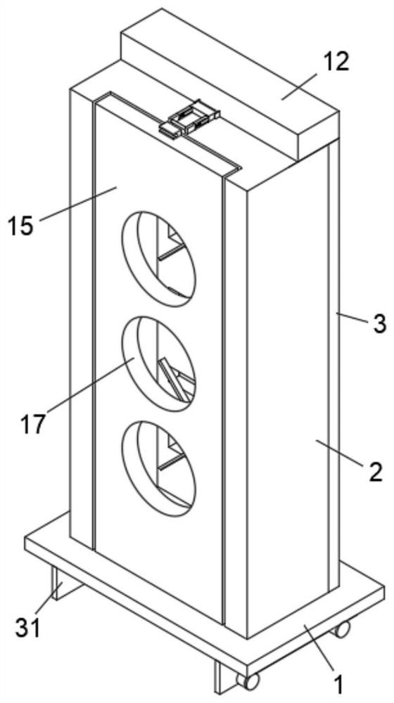
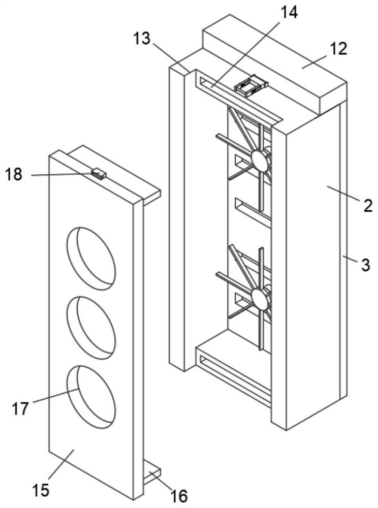
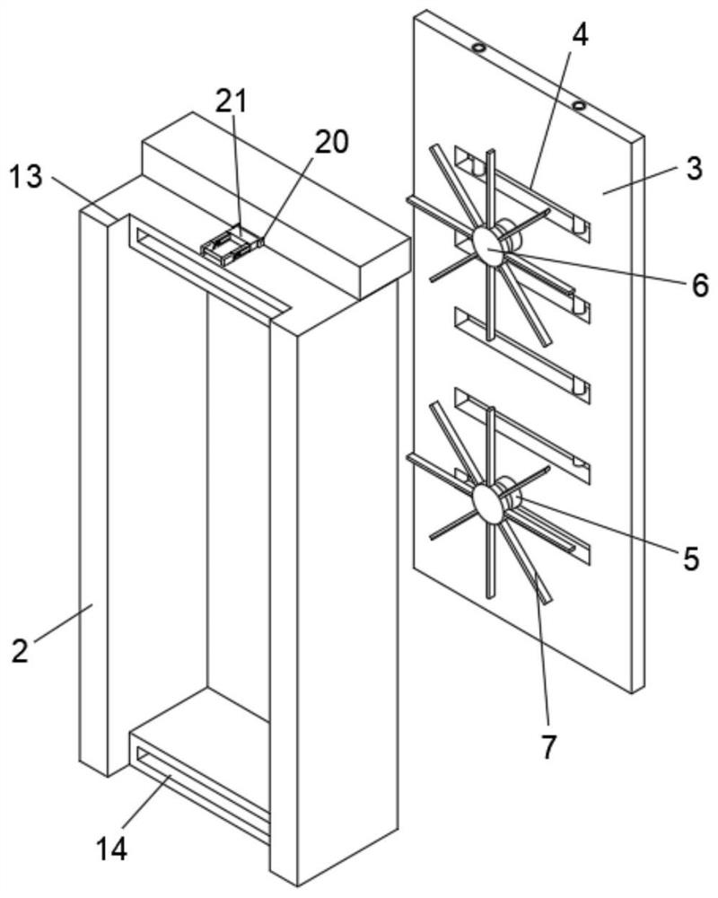
[0028] see Figure 1-7 , a self-cleaning positive pressure ventilation system for industrial plants, comprising a bottom plate 1, the bottom plate 1 is a rectangular structure, the top surface of the bottom plate 1 is fixedly installed with a shell 2, the shell 2 is a rectangular frame structure, and the right side of the shell 2 is fixedly installed There is a right side plate 3, the right side plate 3 is a rectangular structure, the right side plate 3 is pro...


PUM


Abstract

The invention relates to the technical field of industrial factory buildings, and discloses a self-cleaning positive pressure ventilation system of an industrial factory building. The self-cleaning positive pressure ventilation system comprises a bottom plate, a shell is fixedly mounted on the top surface of the bottom plate, the shell is of a rectangular frame structure, a right side plate is fixedly mounted on the right side of the shell, the right side plate is of a rectangular structure, a positive pressure ventilation mechanism is arranged on the right side plate, a detachable mass filtering mechanism is arranged on the left side of the bottom plate, a moving mechanism is arranged on the bottom face of the bottom plate, the positive pressure ventilation mechanism comprises right side ventilation holes, five right side ventilation holes are formed in one side of the right side plate, and two driving motors are fixedly installed on the left side of the right side plate. By arranging the right side plate, the driving motors arranged on the right side plate are started, rotating shafts of the driving motors rotate to drive rotating blocks to rotate, meanwhile, rotating plates are arranged on the rotating blocks, the rotating plates are driven to rotate when the rotating blocks rotate, air flow is generated when the rotating plates rotate, then air on the left side of the device is blown to the left side of the device through the acting force of the rotating plates, and thus the positive pressure ventilation effect is achieved.

Description

technical field [0001] The invention relates to the technical field of industrial plants, in particular to a self-cleaning positive pressure ventilation system for industrial plants. Background technique [0002] Industrial factory buildings refer to various buildings directly used for production or supporting production, including main workshops, auxiliary buildings and ancillary facilities. All factory buildings in industry, transportation, commerce, construction, scientific research, schools and other units should be included. In addition to the workshops used for production, industrial plants also include their auxiliary buildings. [0003] During the normal production and operation of the factory, industrial plants generally need to be ventilated, especially in the production of flammable, explosive and harmful substances during production. In a broad sense, ventilation is to use natural or mechanical methods to make the wind unobstructed. It can pass through and reac...

Claims


Application Information

Patent Timeline
Patent Type & Authority Applications(China)
IPC IPC(8): F24F7/003F24F7/007F24F5/00F24F13/28F24F13/32
CPCF24F7/007F24F5/00F24F13/28F24F13/32
Inventor 周登科董杰曹玉奇
Owner DESIGN INST NO 9 MINISTRY OF MECHINE BUILDING
Why Eureka
Try Eureka