Inspection and calibration device for nuclear power station reactor core liquid level monitoring system

A liquid level monitoring and calibration device technology, applied in the direction of measuring devices, nuclear reactor monitoring, testing/calibration devices, etc., can solve the problem that the inspection of the core liquid level monitoring system and automatic stop of the calibration device cannot be realized, there is a risk of electric shock, and the practicability is not good. To avoid problems such as good or bad, to avoid module damage and overall scrapping, to ensure connection stability, and to avoid loosening of the power interface

Pending Publication Date: 2021-06-15
JIANGSU NUCLEAR POWER CORP
0 Cites 0 Cited by

AI-Extracted Technical Summary

Problems solved by technology

[0005] Aiming at the deficiencies of the prior art, the present invention proposes an inspection and calibration device for the nuclear power plant core liquid level monitoring system to solve the problem that the existing core liquid level monitoring system inspection and calibration device needs to be installed in the core liquid level monitoring system In the cabinet, and there is no fixed module power supply switch, during the inspection, it is necessary to perform power supply and power-off operat...

Abstract

The invention belongs to the technical field of nuclear power station reactor core liquid level monitoring and particularly relates to an inspection and calibration device for a nuclear power station reactor core liquid level monitoring system. The device comprises a calibration simulator, a reactor core liquid level monitoring device, a power supply, a connecting mechanism and a plurality of groups of leads, wherein the reactor core liquid level monitoring device is clamped in the connecting mechanism, a power supply is further arranged in the connecting mechanism, and the power supply is located above the reactor core liquid level monitoring equipment; and a reactor core liquid level monitoring system is mounted in the reactor core liquid level monitoring device. The device is advantaged in that a problem that no fixed module power supply switch exists on the cabinet side of the reactor core liquid level monitoring system is solved, the electric shock risk during operation is reduced, module damage and overall scrapping caused by frequent plugging operation are avoided, automatic timing start and stop of nuclear power plant reactor core liquid level monitoring are achieved through the timer, and practicability is higher.

Application Domain

Engagement/disengagement of coupling partsTesting/calibration apparatus +2

Technology Topic

Nuclear engineeringRadiochemistry +3

Image

  • Inspection and calibration device for nuclear power station reactor core liquid level monitoring system
  • Inspection and calibration device for nuclear power station reactor core liquid level monitoring system
  • Inspection and calibration device for nuclear power station reactor core liquid level monitoring system

Examples

  • Experimental program(1)

Example Embodiment

[0031] The inspection and calibration apparatus of the nuclear power station core level monitoring system will be described in detail below with reference to the accompanying drawings and examples.
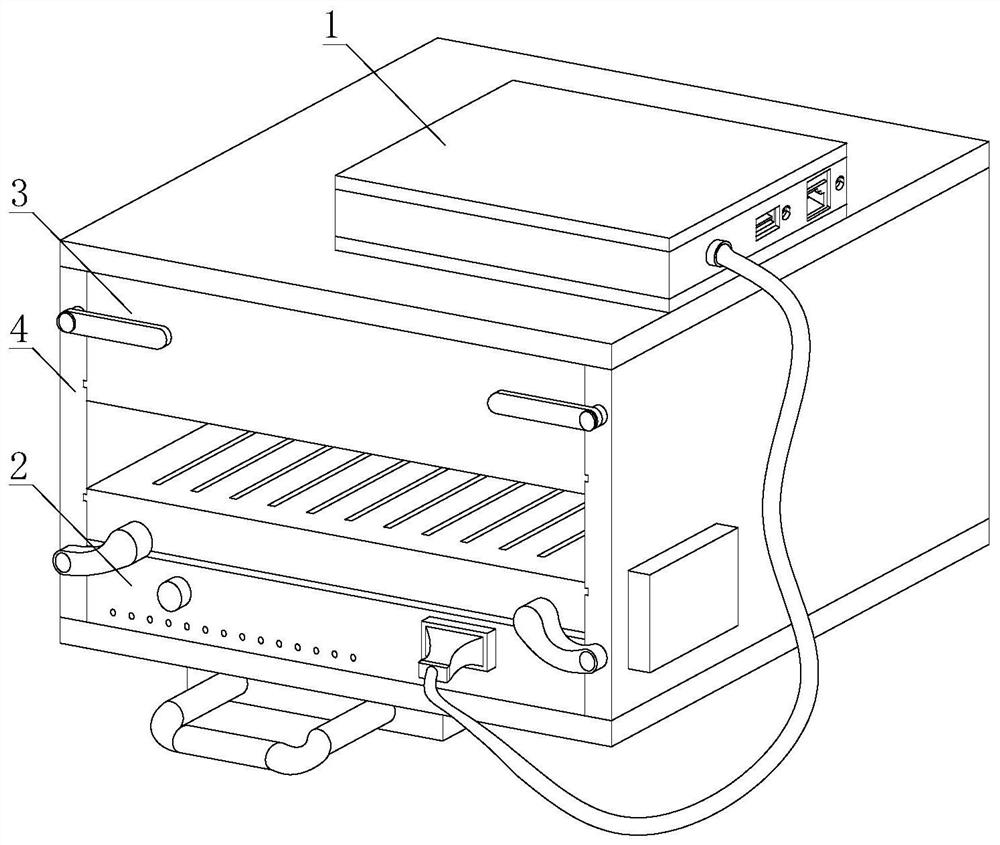
[0032] Such as figure 1 As shown, an inspection and calibration device for a nuclear power plant core level monitoring system includes: a calibration simulator 1, a core level monitoring device 2, a power supply power source 3, a connecting mechanism 4, and a plurality of groups of wires, a calibration simulator 1 With a set of wires, the core level monitor 2 is connected, the core level monitoring device 2 is packaged inside the connecting mechanism 4, and the connection mechanism 4 is also provided with a power supply 3. The power supply 3 is located at a heap. Above the core liquid level monitoring device 2; the inside of the core level monitoring device 2 has a core level monitoring system, the core level monitoring system monitors the core level, and transmits the monitoring data through the data transmission line The calibration simulator 1 is calibrated.
[0033] Such as figure 2 As shown, the connecting mechanism 4 is integrally a hollow long square structure, and the connecting mechanism 4 further includes: a cover housing 41, a chassis 42, a pull ring 43, a plurality of group card grooves 44, a timer 45, a lower limit assembly 46, The upper limit assembly 47 and the backplane assembly 48;
[0034] The outer cover housing 41 is symmetrically processed on the two-symmetric inner wall surface perpendicular to the ground, and the lower two sets of card slots 44, the lower group card groove 44 and the core level monitoring device 2 is attached, and the lower column card groove 44 pair core The vertical position of the liquid level monitoring device 2 is defined, and the upper group card groove 44 is attached to the power supply power source 3, and the power supply power 3 is loaded into the outer cover housing 41 inside the outer casing 41 by the upper set of card slots 44. The card slot 44 defines the vertical position of the power supply power 3;
[0035] The bottom fixing of the outer cover housing 41 is fixed to the bottom frame 42, the bottom frame 42 is fixedly coupled to the pull ring 43, and the outer cover housing 41 is fixed to the upper outer wall surface of the outer surface of the ground plane, and the timer 45 is fixedly mounted. The device 45 is connected to the lower limit bit assembly 46 and the upper limit assembly 47 by two sets of wires;
[0036] Such as image 3 with Figure 6As shown, both the lower assembly 46 and the upper unit 47 are mounted on the side wall surface of the two-symmetric wall surface perpendicular to the ground plane, and the lower part assembly 46 is located below the upper limit assembly 47;
[0037] The outer cover housing 41 is mounted on the inner wall of one side of the timer 45 to fix the back plate assembly 48.
[0038] The lower limit assembly 46 is two groups, and the two sets of lower limit assembly 46 are symmetrically mounted the lower end of the side wall surface of the outer cover housing 41 and the ground plane perpendicular; the lower limit assembly 46 of each set includes: shake The sheet 461, the sensor 462, the connecting 463, and the motor 464; one end of the shake piece 461 is connected to the motor 464 by a connecting 463; the connecting 463 is provided with a sensor 462.
[0039] The motor 464 is mounted inside the outer cover housing 41 and the side wall surface of the two-symmetric wall surface perpendicular to the ground, and the output of the motor 464 is mounted outside the outer cover of the outer cover housing 41 and the surface of the surface of the ground plane. The connecting 463 is fixedly connected, and the connecting 463 is welded to the end of the shake piece 461.
[0040] Such as Figure 4 As shown, the upper limit assembly 47 is two groups, and the upper limit assembly 47 is configured to be mounted on the upper end of the side wall surface of the two-symmetric wall surface perpendicular to the surface phase, the upper limit assembly 47 including The cylinder rod 471, the diaphragi 472, and the cylinder 473, the entrance to the cylinder 473 fixedly mounted inside the side wall surface of the outer cover housing 41 and the surface of the surface of the surface, and the output terminal of the cylinder 473 and the end of the cylinder rod 471 are fixed. The connection and disposed inside the side wall surface of the two-symmetric wall surface perpendicular to the outer cover housing 41 and the ground plane, the other end of the cylinder rod 471 is disposed outside the outer cover of the outer cover housing 41 and the surface of the two-symmetric wall surface of the ground plane. Picking 472 is fixed.
[0041] Figure 5 As shown, the backplane assembly 48 includes a back plate body 481, a pair of tank 482, a monitoring device card assembly 483, a monitoring device switch 484, a plurality of elastic push plate 485, a power interface 486, a power switch 487, and a number of groups of wires ;
[0042] The upper portion of the surface of the backing plate body 481 has a pair of tank 482, and the power switch 487, the power supply interface 486, and the two elastic push plates 485 are respectively disposed on the surface of the docking groove 482;
[0043] The lower portion of the back plate body 481 is provided with a monitoring device card assembly 483, a monitoring device switch 484, and two elastic push plates 485; the monitoring device card assembly 483 is connected to the core level monitoring device 2, monitoring The device card assembly 483 is electrically connected to the monitoring device switch 484, and the lower portion of the surface and the elastic push plate 485 on the tank 482 are symmetrical.
[0044] The power interface 486 is electrically connected to the monitoring device card assembly 483, and the power supply interface 486 is also connected to the power supply power source 3; the power switch 487 electrically connects to the power supply interface 486.
[0045] The embodiment of the present invention will be described in detail above, and the present invention is not limited to the above examples, and various changes can be made without departing from the purposes of the invention.

PUM

no PUM

Description & Claims & Application Information

We can also present the details of the Description, Claims and Application information to help users get a comprehensive understanding of the technical details of the patent, such as background art, summary of invention, brief description of drawings, description of embodiments, and other original content. On the other hand, users can also determine the specific scope of protection of the technology through the list of claims; as well as understand the changes in the life cycle of the technology with the presentation of the patent timeline. Login to view more.

Similar technology patents

Ultra-thin special water-based ink for gravure printing and preparation method thereof

PendingCN114574032AEnsure connection stabilitygood effect
Owner:江苏卫星新材料股份有限公司

Roof mounting structure

InactiveCN111962736AEasy splicingEnsure connection stability
Owner:XIJING UNIV

Special label for cylindrical tubing couplings and mounting method thereof

PendingCN108288086AGuaranteed positional stabilityPrevent falling off
Owner:东营杰开智能科技有限公司

New energy electric vehicle battery quick connector

ActiveCN113991364AEnsure connection stabilityprevent loosening
Owner:CHY TECH HUBEI TECH CO LTD

Water surface garbage salvaging and collecting device

InactiveCN112339920AEnsure connection stability
Owner:陆天祥

Manufacturing equipment and method for stylus tip capable of ensuring centering of insert

PendingCN114347361AGuaranteed positional stabilityGuaranteed accuracy
Owner:GUANGDONG GREEN PRECISION COMPONENTS CO LTD

Angle radar fixing support and fixing method

PendingCN114802024AEnsure connection stabilitylow wear
Owner:VOYAH AUTOMOBILE TECH CO LTD

Classification and recommendation of technical efficacy words

  • Guaranteed positional stability

Special label for cylindrical tubing couplings and mounting method thereof

PendingCN108288086AGuaranteed positional stabilityPrevent falling off
Owner:东营杰开智能科技有限公司

Manufacturing equipment and method for stylus tip capable of ensuring centering of insert

PendingCN114347361AGuaranteed positional stabilityGuaranteed accuracy
Owner:GUANGDONG GREEN PRECISION COMPONENTS CO LTD
Why Eureka
Try Eureka