Channel detection equipment and main control board

A channel detection and main control board technology, which is applied in geophysical measurement, electromagnetic wave detection, instruments, etc., can solve the problems of interval installation, etc., and achieve the advantages of reduced floor space, good compatibility and expandability, and convenient installation Effect

Active Publication Date: 2021-06-15
HANGZHOU RAYIN TECH CO LTD
View PDF12 Cites 0 Cited by
  • Summary
  • Abstract
  • Description
  • Claims
  • Application Information

AI Technical Summary

Problems solved by technology

[0004] The present invention provides a channel detection device to solve the problem that adjacent detection doors need to be installed at intervals

Method used


Image

  • Channel detection equipment and main control board
  • Channel detection equipment and main control board
  • Channel detection equipment and main control board

Examples


Embodiment Construction

[0067] In order to make the purpose, technical means and advantages of the present application clearer, the present application will be further described in detail below in conjunction with the accompanying drawings.

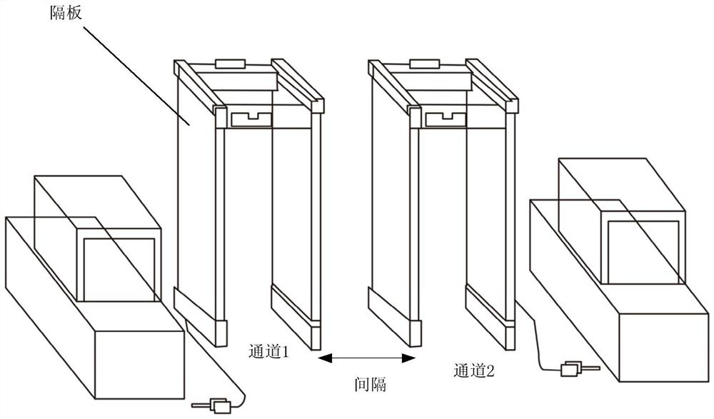
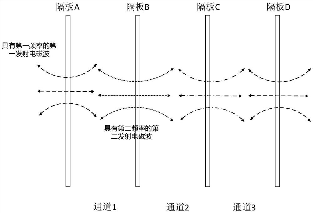
[0068] The present application uses partitions to separate the passages, so that the passages are adjacent to each other. The adjacency means that the distance between two adjacent passages is 0. By making the passages distribute electromagnetic waves of different frequencies, the gap between the two adjacent passages is avoided. The interference of induced electromagnetic waves solves the problem that adjacent detection doors need to be installed at intervals, and realizes the target detection of multiple adjacent channels.

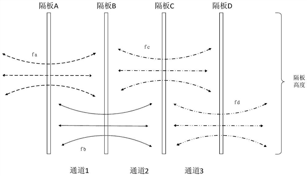
[0069] see figure 2 as shown, figure 2 It is a schematic front view of the channel detection device of the present application. The transmitting electromagnetic wave frequencies emitted by the transmitting coils in the partitions of at...


PUM


Abstract

The invention discloses channel detection equipment. The equipment comprises at least three partition plates, at least two channels are formed between every two adjacent partition plates, and the same partition plate is arranged between every two adjacent channels. Each partition plate is provided with a transmitting coil used for transmitting electromagnetic waves and a receiving coil used for receiving and sensing the transmitted electromagnetic waves to generate induced electromagnetic waves, and the frequencies of the transmitted electromagnetic waves transmitted by the transmitting coils in the partition plates of at least two adjacent channels are different, so each channel is provided with a first emission electromagnetic wave with a first frequency from a first partition plate in the partition plates on the two sides of the channel and a second emission electromagnetic wave with a second frequency from a second partition plate; and in each channel, a first induced electromagnetic wave signal induced to the first transmitted electromagnetic wave and a second induced electromagnetic wave signal induced to the second transmitted electromagnetic wave are used for detection. The problem that adjacent detection doors need to be installed at intervals is solved, and the occupied space when the channel detection equipment is installed is reduced.

Description

technical field [0001] The invention relates to the field of metal detection, in particular to a channel detection device. Background technique [0002] The metal detection equipment applied to the channel, such as the detection door, mainly consists of partitions located on both sides of the channel, and a chassis located on the top of the two partitions, forming a "冂" shaped channel structurally. There are alternating magnetic field transmitting or receiving coils on both sides of the partition, or there are transmitting and receiving coils at the same time. When a metal object passes through the middle of the door body, due to the symmetry of the eddy current of the metal coil, the properties on both sides of the partition are the same. In general, there are infrared detectors installed on the partitions on both sides through direct radiation or through reflection, which are used to count the number of people, judge the direction, detect flying objects and shield interfe...

Claims


Application Information

Patent Timeline
Patent Type & Authority Applications(China)
IPC IPC(8): G01V11/00G01V8/20G01V3/12
CPCG01V11/00G01V3/12G01V8/20
Inventor 张国欣李国锋
Owner HANGZHOU RAYIN TECH CO LTD
Why Eureka
Try Eureka