Blade reinforcing edge nose cone width detection system and detection method
A detection system and nose cone technology, which is applied in the direction of measuring devices, instruments, and electrical devices, can solve the problems of difficult edge processing and nose cone processing, and achieve the effect of solving the problem of rapid quality inspection and simple inspection process
- Summary
- Abstract
- Description
- Claims
- Application Information
AI Technical Summary
Problems solved by technology
Method used
Image
Examples
no. 1 example
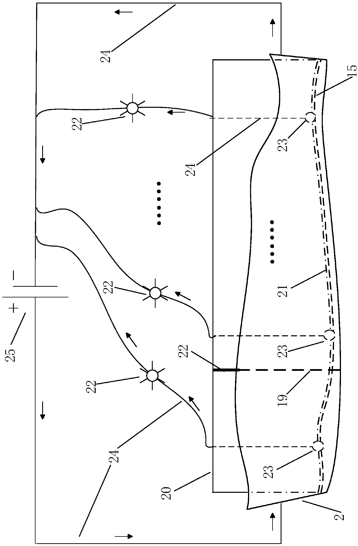
[0046] like image 3 As shown, in the first embodiment of the detection system, the detection system for detecting the width of the metal reinforced side nose cone includes an insulating detection body 20 and a detection circuit. The detection body 20 is an insulator, and its material may be a relatively rigid insulating material, such as engineering plastics, wood, etc., but it is not limited thereto. The shape of the detection body 20 can be processed according to the standard shape of the metal reinforcement edge. The exterior of the detection body 20 is provided with a plurality of conductive contacts 23 distributed along the extension direction of the detection body 20, and the conductive contacts 23 can contact with corresponding positions on the inner surface 15 of the metal reinforced edge nose cone with acceptable width. The specific structure of the detection body 20 may be that the detection body 20 includes at least one insulation detection section whose outer sur...
no. 2 example
[0051] In the second embodiment, the same parts as those in the first embodiment will not be described again.
[0052] like Figure 4 As shown, compared with the first embodiment, each of the plurality of conductive contacts 23 in the second embodiment is connected in series with the indicator light 22 that receives the detection signal corresponding to its output to form a group of primary electrical components. Group the first-level electric element, and the second-level electric element that is formed in parallel with the rest of the first-level electric element is connected in series, after closing the switch 30, if two or more than two conductive contacts 23 are attached to the inner surface 15 of the nose cone, The corresponding indicator light 22 will light up only when the external power supply 25 forms a closed circuit through the conductive wire 24 . The function of resistor 29 is mainly to prevent short circuit. Compared with the first embodiment, the characterist...
no. 3 example
[0054] In the third embodiment, the same parts as those in the first embodiment will not be described again.
[0055] like Figure 5 As shown, the circuit is completely installed in the detection body 20 . A plurality of detection signals output by the plurality of conductive contacts 23 are coupled through a logic “AND” gate 28 , and a final detection signal is output to the indicator light 22 .
[0056] The specific working principle is as follows: only when the contacts 23 of the first / 2 / 3 detection points are all attached to the inner surface 15 of the nose cone, the output terminal of the first logic "AND" gate 28 outputs a high voltage signal as One input signal of the next logic "AND" gate 28; the other input signal comes from the 4th detection point. By analogy, until the two input signals of the last logic "AND" gate 28 are both high-voltage states, the indicator light 22 is lit. At this time, it shows that the nose cone width of the entire reinforced edge is quali...
PUM
 Abstract
Description
Claims
Application Information
 - R&D
- Intellectual Property
- Life Sciences
- Materials
- Tech Scout
- Unparalleled Data Quality
- Higher Quality Content
- 60% Fewer Hallucinations
Browse by: Latest US Patents, China's latest patents, Technical Efficacy Thesaurus, Application Domain, Technology Topic, Popular Technical Reports.
© 2025 PatSnap. All rights reserved.Legal|Privacy policy|Modern Slavery Act Transparency Statement|Sitemap|About US| Contact US: help@patsnap.com


