Prosthesis extractor for hip joint replacement
A hip joint replacement and extractor technology, which is applied in the directions of hip joints, joint implants, joint implants, etc., can solve the problem that the hip joint prosthesis is not easy to take out.
- Summary
- Abstract
- Description
- Claims
- Application Information
AI Technical Summary
Problems solved by technology
Method used
Image
Examples
Embodiment 1
[0033] Embodiment 1 A kind of prosthesis extractor for hip arthroplasty
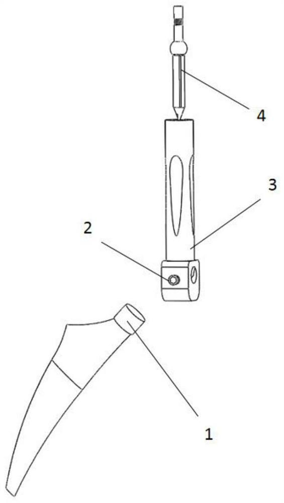
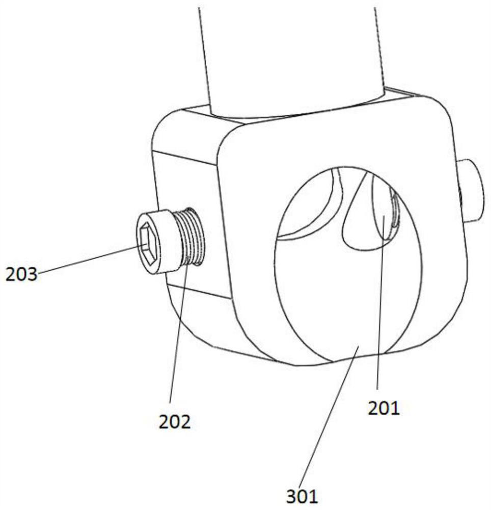
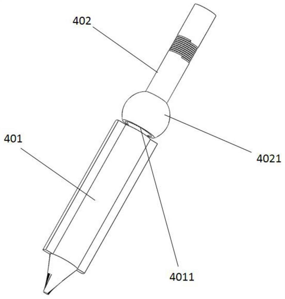
[0034] A prosthesis extractor for hip joint replacement, which includes: a cylinder 3 clamping the cylindrical section of the hip joint prosthesis 1; it is characterized in that the first end of the cylinder 3 is sleeved on the cylindrical section of the prosthesis, and Along the radial direction of the cylinder body 3, the long rod 2 for radially locking the cylindrical section of the prosthesis is arranged on the side wall of the cylinder body 3; the long rod 2 is set as a threaded rod 202 that moves radially along the cylinder body 3, and Threads engaged with the threaded rod 202 are set through the side wall of the cylinder body 3; along the axial direction of the cylinder body 3, an axial locking mechanism 4 for axially locking the cylindrical section of the prosthesis is provided in the cylinder body 3; A draw-in groove 304 for the doctor to grab the cylinder body 3 is set on the outer wall of the ...
Embodiment 2
[0040] Embodiment 2 A kind of prosthesis extractor for hip arthroplasty
[0041] A prosthesis extractor for hip joint replacement, which includes: a cylinder 3 clamping the cylindrical section of the hip joint prosthesis 1; it is characterized in that the first end of the cylinder 3 is sleeved on the cylindrical section of the prosthesis, and Along the radial direction of the cylinder body 3, the long rod 2 for radially locking the cylindrical section of the prosthesis is arranged on the side wall of the cylinder body 3; the long rod 2 is set as a threaded rod 202 that moves radially along the cylinder body 3, and Threads engaged with the threaded rod 202 are set through the side wall of the cylinder body 3; along the axial direction of the cylinder body 3, an axial locking mechanism 4 for axially locking the cylindrical section of the prosthesis is provided in the cylinder body 3; A draw-in groove 304 for the doctor to grab the cylinder body 3 is set on the outer wall of the cy...
Embodiment 3
[0046] Embodiment 3 A kind of prosthesis extractor for hip replacement
[0047] A prosthesis extractor for hip joint replacement, which includes: a cylinder 3 clamping the cylindrical section of the hip joint prosthesis 1; it is characterized in that the first end of the cylinder 3 is sleeved on the cylindrical section of the prosthesis, and Along the radial direction of the cylinder body 3, the long rod 2 for radially locking the cylindrical section of the prosthesis is arranged on the side wall of the cylinder body 3; the long rod 2 is set as a threaded rod 202 that moves radially along the cylinder body 3, and Threads engaged with the threaded rod 202 are set through the side wall of the cylinder body 3; along the axial direction of the cylinder body 3, an axial locking mechanism 4 for axially locking the cylindrical section of the prosthesis is provided in the cylinder body 3; A draw-in groove 304 for the doctor to grab the cylinder body 3 is set on the outer wall of the c...
PUM
 Abstract
Description
Claims
Application Information
 - R&D
- Intellectual Property
- Life Sciences
- Materials
- Tech Scout
- Unparalleled Data Quality
- Higher Quality Content
- 60% Fewer Hallucinations
Browse by: Latest US Patents, China's latest patents, Technical Efficacy Thesaurus, Application Domain, Technology Topic, Popular Technical Reports.
© 2025 PatSnap. All rights reserved.Legal|Privacy policy|Modern Slavery Act Transparency Statement|Sitemap|About US| Contact US: help@patsnap.com


