Printing and dyeing stirring equipment

A technology of mixing equipment and mixing tank, which is applied in the direction of mixer accessories, mixers with rotating stirring devices, dissolving, etc., can solve the problems of affecting the service life of precision parts of equipment, reducing the utilization efficiency of dyes, and insufficient mixing of dyes, etc., to achieve Effects that improve convenience, avoid cracks or bends, and avoid clogging

Active Publication Date: 2021-06-18
CHANGZHOU MIXON MIXING EQUIP CO LTD
View PDF5 Cites 0 Cited by
  • Summary
  • Abstract
  • Description
  • Claims
  • Application Information

AI Technical Summary

Problems solved by technology

[0006]Aiming at the deficiencies of the prior art, the present invention provides a printing and dyeing mixing equipment, which solves the problem of easy mistakes in the working process, which makes the mixing of the dyes insufficient and reduces the dyeing Utilization efficiency, the vibration generated by the equipment during operation, affects the service life of the precision parts inside the equipment, thus reducing the practicability of the device

Method used


Image

  • Printing and dyeing stirring equipment
  • Printing and dyeing stirring equipment
  • Printing and dyeing stirring equipment

Examples


Embodiment 1

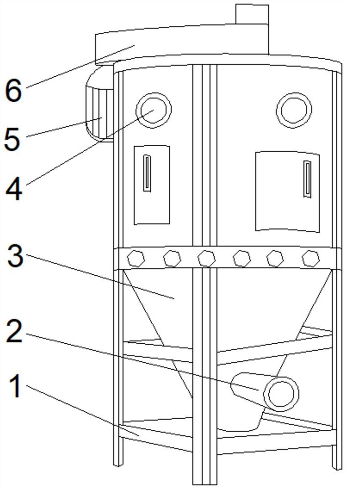
[0033] see Figure 1-2 , the present invention provides a technical solution: a printing and dyeing mixing equipment, including a fixed frame 1, the top of the inner wall on both sides of the fixed frame 1 is fixedly connected with a stirring device 3, and the top of the stirring device 3 is provided with an agitator 6, The top of the left outer wall of the agitator 6 is fixedly connected with a motor 5, the output shaft of the motor 5 is connected with the agitator 6 in rotation, the front and top sides of the agitator 3 are provided with a feed port 4, and the right side of the front bottom of the agitator 3 is connected. There are feed pipes 2.

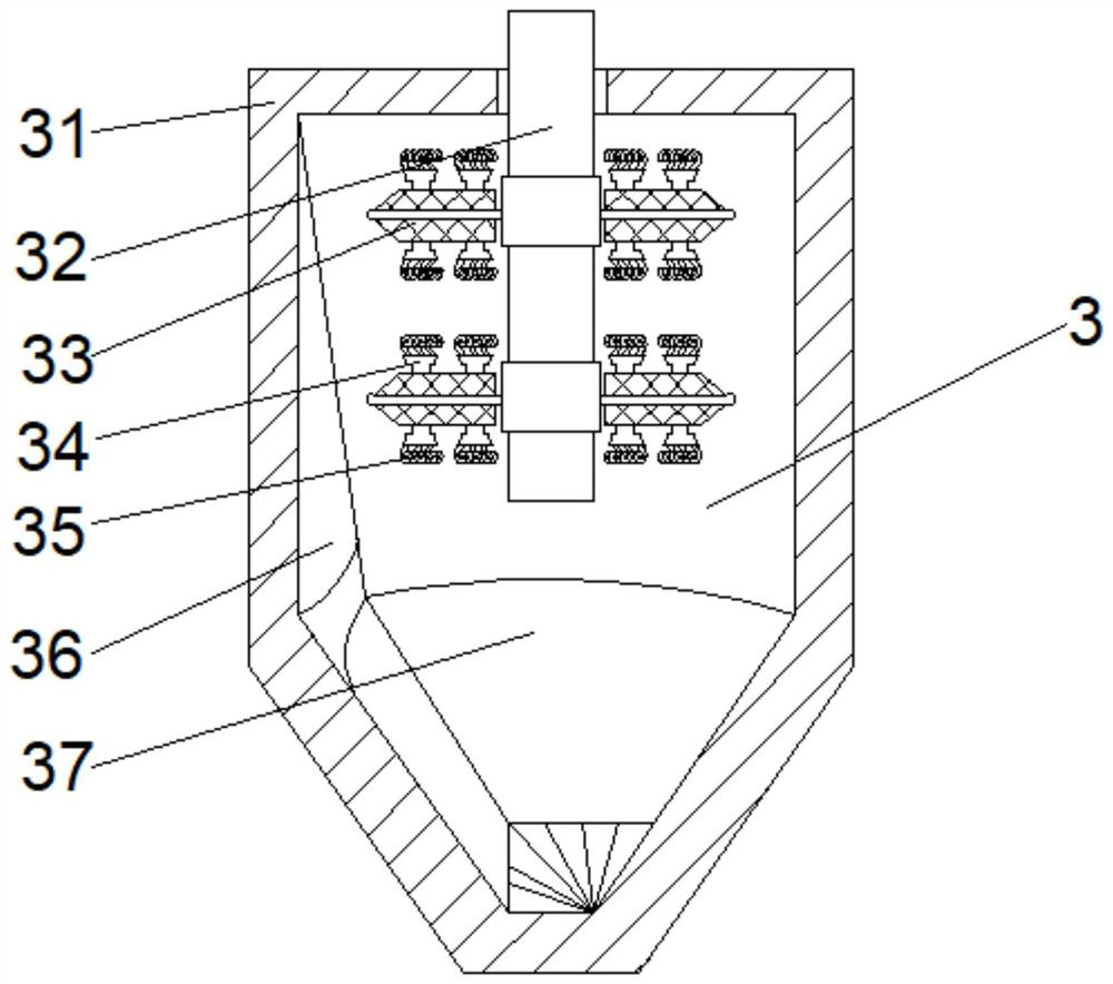
[0034]Wherein, the stirring device 3 includes a stirring tank 31, a stirring shaft 32 is arranged in the middle of the top of the inner chamber of the stirring tank 31, the top of the stirring shaft 32 runs through the stirring tank 31 and extends to the outside of the stirring tank 31, the outer walls of the two sides of the stirr...

Embodiment 2

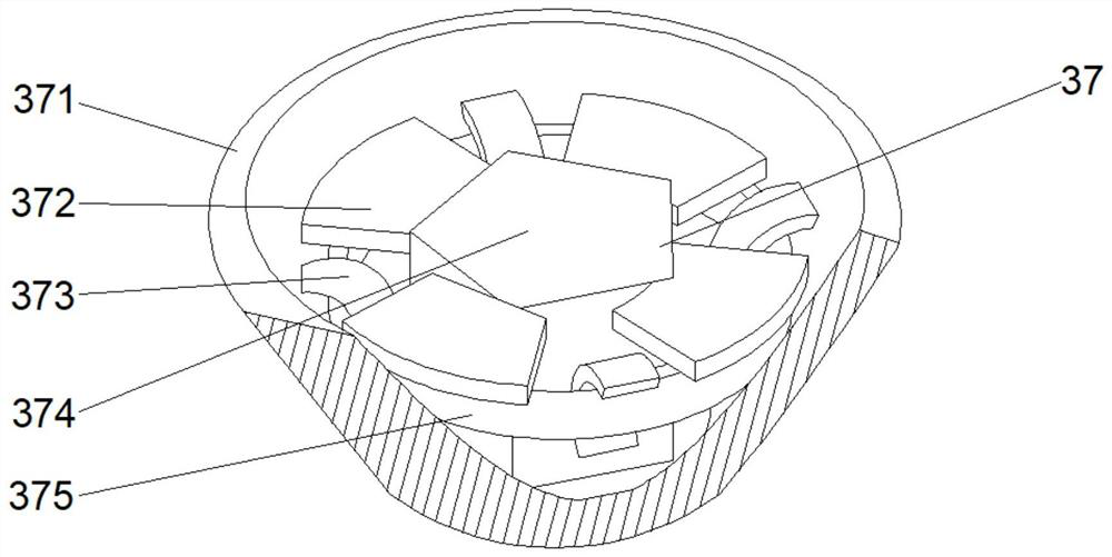
[0037] see Figure 1-4 On the basis of Embodiment 1, the present invention provides a technical solution: the fixing mechanism 37 includes a housing 371, the middle position of the inner cavity bottom of the housing 371 is fixedly connected with an auxiliary mechanism 374, and the top of the outer walls on both sides of the auxiliary mechanism 374 is fixedly connected with The swing plate 372 is provided with an adjustment ring 375 on the top of both sides of the inner wall of the housing 371 .

[0038] Among them, the auxiliary mechanism 374 includes an auxiliary frame d1, the top two sides of the auxiliary frame d1 are fixedly connected with a force-bearing block d7, the bottom of the force-bearing block d7 is provided with an elastic ball d6, and the top sides of the auxiliary frame d1 are located on the sides of the force-bearing block d7. The bottom is fixedly connected with the block d5, the bottom of the block d5 is provided with a rolling ring d3, the left outer wall o...

Embodiment 3

[0041] see Figure 1-6 , on the basis of Embodiment 1 and Embodiment 2, the present invention provides a technical solution: the guide mechanism d4 includes a guide frame d41, the top of the guide frame d41 is fixedly connected with a blocking block d44, and the top of the inner cavity of the guide frame d41 is fixedly connected There is an inner connection block d43, the top of the inner cavity of the guide frame d41 is located on both sides of the inner connection block d43 and is fixedly connected with extruding rods d42, and the bottom of the guide frame d41 is fixedly connected with a force plate d45.

[0042] Wherein, the force receiving plate d45 includes a plate body t1, the two sides of the top of the plate body t1 are fixedly connected with telescopic ends t2, and the middle position of the bottom of the plate body t1 is provided with a groove t3.

[0043] When in use, the telescopic end t2 on the plate body t1 can play a fixed role, and it is easy to shrink under pr...


PUM


Abstract

The invention discloses printing and dyeing stirring equipment. The equipment comprises a fixing frame, stirring devices are fixedly connected to the tops of the inner walls of the two sides of the fixing frame, a stirrer is arranged at the top of each stirring device, a motor is fixedly connected to the top of the outer wall of the left side of the stirrer, the output shaft of the motor is rotationally connected with the stirrer, feeding ports are formed in the two sides of the top of the front face of the stirring device, and the right side of the bottom of the front face of the stirring device communicates with a feeding pipe. On one hand, the printing and dyeing stirring equipment can be tightly matched with collecting wires to facilitate smashing and dissolving of some undissolved accumulated residues, so that the interior of the device can achieve full reaction; and on the other hand, floating impurities and foam can be collected and treated, so that the influence on work is avoided, the stability of the device is improved, the strength of the device is improved, the situation that internal precision parts are cracked or bent is avoided, and the service life of the device is further prolonged.

Description

technical field [0001] The invention relates to the technical field of printing and dyeing equipment, in particular to a printing and dyeing stirring equipment. Background technique [0002] With the development of society and the continuous advancement of science and technology, more and more equipment is used by all walks of life, which greatly reduces the labor intensity of people's production and life. In the field of textile technology, the production of fabrics requires many processes to work together. Complete, and in these processes, the dyeing of the cloth can dye the cloth, not only can make the color of the cloth more vivid, but also increase the color types of the cloth, and when the cloth is dyed, the dye needs to be adjusted according to the needs , to mix and stir the dye. [0003] According to a printing and dyeing dye mixing device disclosed in Chinese Patent No. CN108479516A, a raw material weight display screen is installed on the upper part of the right ...

Claims


Application Information

Patent Timeline
IPC IPC(8): B01F7/18B01F7/00B01F15/00
CPCB01F27/171B01F27/90B01F35/145B01F2101/30
Inventor 李海旺
Owner CHANGZHOU MIXON MIXING EQUIP CO LTD
Why Eureka
Try Eureka