Simple and convenient brake disc manufacturing and forming device

A molding device and brake disc technology, which is applied in the direction of manufacturing tools and other manufacturing equipment/tools, can solve the problems of potential safety hazards, time-consuming and labor-intensive problems, and achieve the effect of shortening the contact distance

Active Publication Date: 2021-06-18
江西樟树市福铃内燃机配件有限公司
View PDF7 Cites 1 Cited by
  • Summary
  • Abstract
  • Description
  • Claims
  • Application Information

AI Technical Summary

Problems solved by technology

[0003] The punching process of the brake disc is generally pushed by the staff to the metal disc, which is pushed to the bottom of the punching machine, and the punching machine moves up and down to punch the metal disc. It is time-consuming and labor-intensive to polish the hole marks on the surface of the disk in the later stage, and there are potential safety hazards. Therefore, it is necessary to design a machine that does not need to be pushed by hand to ensure safety. It can polish the punched metal disk in real time without reprocessing in the later stage Simple Brake Disc Manufacturing and Forming Device

Method used


Image

  • Simple and convenient brake disc manufacturing and forming device
  • Simple and convenient brake disc manufacturing and forming device
  • Simple and convenient brake disc manufacturing and forming device

Examples


Embodiment 1

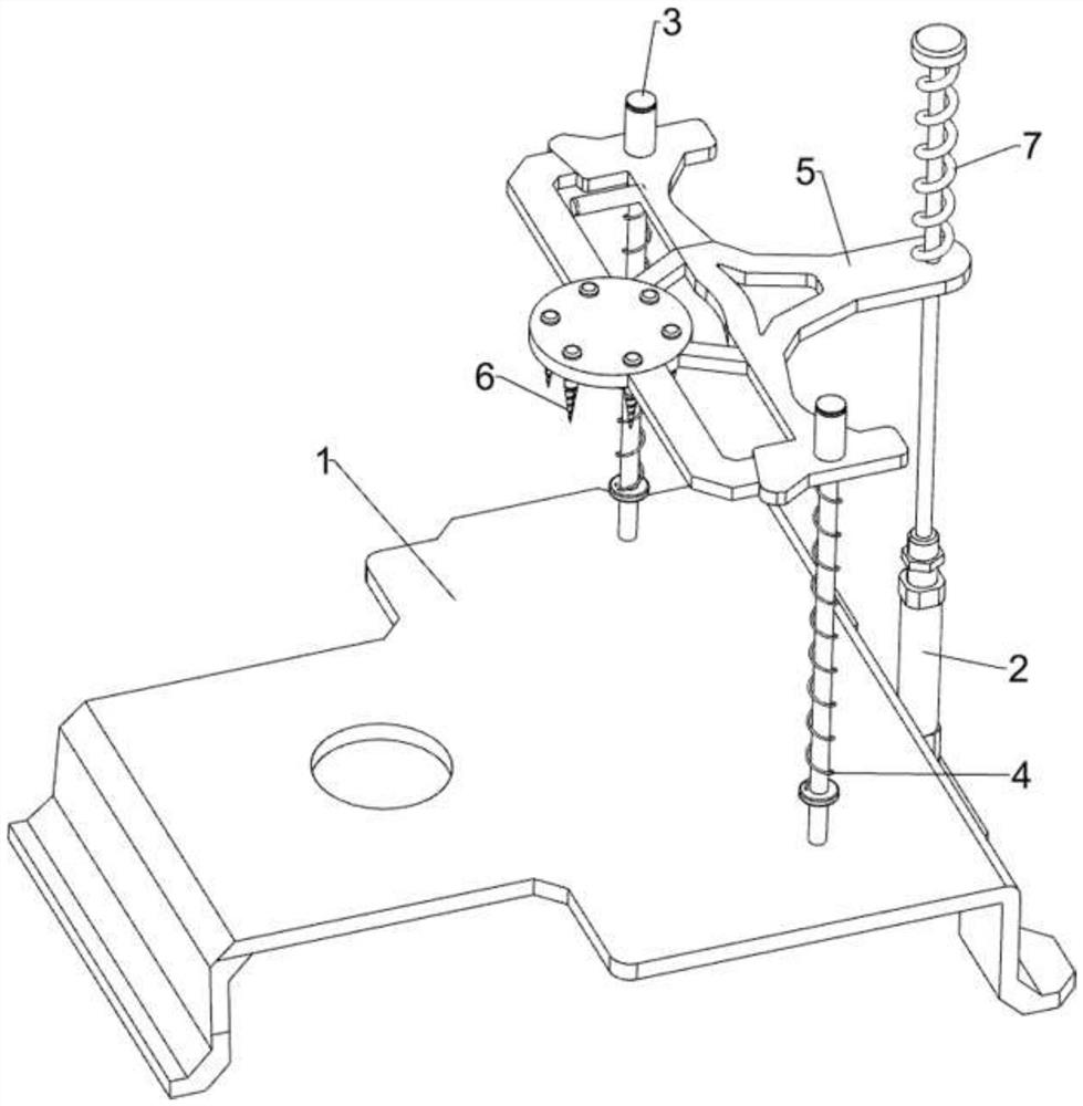
[0045] A simple brake disc manufacturing molding device, such as figure 1 and figure 2 As shown, it includes a bottom plate 1, a cylinder 2, a first fixed rod 3, a first spring 4, a pressure plate 5, a drilling machine 6, a second spring 7, a pushing mechanism 8 and a feeding mechanism 9, and the top right side of the bottom plate 1 A cylinder 2 is provided, first fixed rods 3 are provided on the front and rear sides of the top of the bottom plate 1, and a pressing plate 5 is slidably arranged between the first fixed rods 3, and the pressing plate 5 is slidably connected to the telescopic rod of the cylinder 2 and is connected to its top. The second spring 7 is connected, the first spring 4 is connected between the bottom of the pressing plate 5 and the first fixed rod 3, the drilling machine 6 is arranged on the left side of the pressing plate 5, and the pushing mechanism 8 is arranged on the top of the bottom plate 1, and the pushing mechanism 8 The left part is connected ...

Embodiment 2

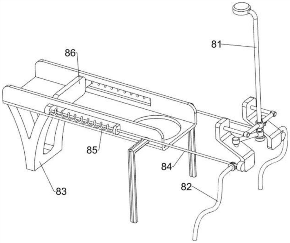
[0048] On the basis of Example 1, such as image 3 and Figure 4 As shown, the pushing mechanism 8 includes a first pressing bar 81, a wheel bar 82, a material pushing frame 83, a rope 84, a third spring 85 and a push plate 86, and the right side of the bottom plate 1 is symmetrically provided with a wheel bar 82, and the wheel bar 82 tops are provided with wheels, and the telescopic end of cylinder 2 is connected with the first depression bar 81, and base plate 1 top is provided with pusher frame 83, and push plate 86 is provided with sliding type on the pusher frame 83, and the right side of push plate 86 all walks around Two ropes 84 are connected between the wheel and the first depression bar 81 , and two third springs 85 are connected between the right side of the push plate 86 and the push frame 83 .

[0049] The blanking mechanism 9 includes a first fixed block 91, a blanking frame 92, a push block 93, a baffle plate 94 and a fourth spring 95, and the front and rear si...

Embodiment 3

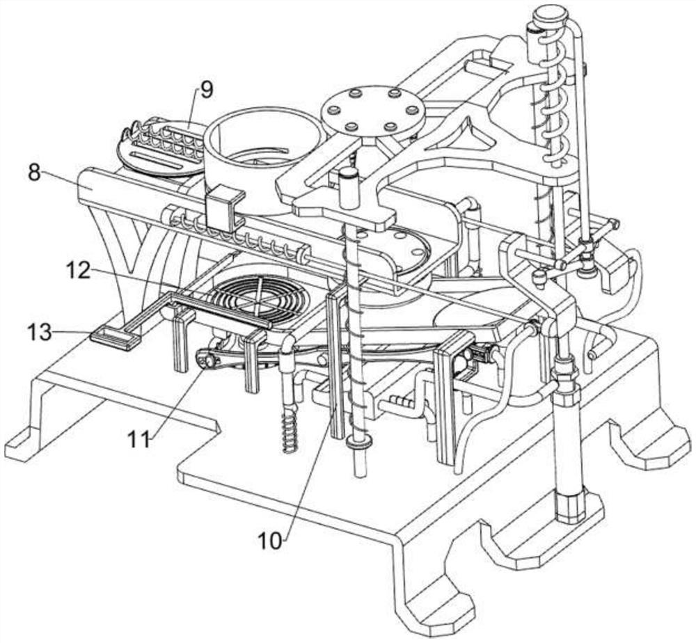
[0052] On the basis of Example 2, such as Figure 5 to Figure 8 As shown, a clamping mechanism 10 is also included. The clamping mechanism 10 includes a guide rod 101, an inclined block 102, a fifth spring 103, a lifting frame 104, a sixth spring 105 and a clamping disc 106. The top of the bottom plate 1 is provided with 3 A guide bar 101, between the guide bars 101 is slidingly provided with an inclined block 102, the fifth spring 103 is connected between the inclined block 102 and the right part of the guide bar 101, the top of the base plate 1 is symmetrically provided with a lifting frame 104, the lifting frame 104 The telescopic end sleeve is provided with a sixth spring 105, and a clamping disc 106 is connected between the tops of the elevating frame 104, and the clamping disc 106 is slidably connected with the right part of the pushing frame 83.

[0053] The telescopic rod of cylinder 2 shortens and extrudes the inclined block 102 to move to the left under the guidance ...


PUM


Abstract

The invention relates to a manufacturing and forming device, in particular to a simple and convenient brake disc manufacturing and forming device. According to the simple and convenient brake disc manufacturing and forming device, manual pushing is not needed, safety is guaranteed, a punched metal disc is polished in real time, and later machining is not needed. The simple and convenient brake disc manufacturing and forming device comprises an air cylinder, a first fixing rods, a first spring and a drilling machine, wherein the air cylinder is arranged on one side of the top of a bottom plate; the first fixing rods are arranged on the two sides of the top of the bottom plate, a pressing plate is slidably arranged between the first fixing rods, the pressing plate is slidably connected with a telescopic rod of the air cylinder, and a second spring is connected between the pressing plate and the top end of the pressing plate; the first spring is connected between the bottom of the pressing plate and the first fixing rod; and the drilling machine is arranged on one side of the pressing plate. The drilling machine is driven to move up and down in a reciprocating mode to make contact with the metal disc and drill the metal disc, and the basic function of the device is achieved.

Description

technical field [0001] The invention relates to a manufacturing and forming device, in particular to a simple brake disc manufacturing and forming device. Background technique [0002] The brake disc is the brake disc, which is a metal disc, which is made of alloy steel and fixed on the wheel. It rotates with the wheel. When the vehicle is on the brakes, the brake calipers clamp the brake disc to slow down or stop. , Generally, there are round holes on the brake disc, and its function is to reduce weight and increase friction. [0003] The punching process of the brake disc is generally pushed by the staff to the metal disc, which is pushed to the bottom of the punching machine, and the punching machine moves up and down to punch the metal disc. It is time-consuming and labor-intensive to polish the hole marks on the surface of the disk in the later stage, and there are potential safety hazards. Therefore, it is necessary to design a machine that does not need to be pushed ...

Claims


Application Information

Patent Timeline
Patent Type & Authority Applications(China)
IPC IPC(8): B23P23/04
CPCB23P23/04
Inventor 黄建民
Owner 江西樟树市福铃内燃机配件有限公司
Why Eureka
Try Eureka