Push-pull type printing system and continuous ink-jet printing machine

An inkjet printing machine and printing system technology, applied to typewriters, printing, transfer materials, etc., can solve the problems of inconvenient daily maintenance of the nozzle assembly, the nozzle assembly cannot be pulled out as a whole, and the nozzle assemblies are not parallel to each other, etc., to achieve positioning Good locking effect, fewer parts, and improved printing quality

Active Publication Date: 2021-06-18
HANGZHOU HONGHUA DIGITAL TECH
View PDF11 Cites 1 Cited by
  • Summary
  • Abstract
  • Description
  • Claims
  • Application Information

AI Technical Summary

Problems solved by technology

[0002] The continuous inkjet printing machine solves the shortcomings of low production efficiency and slow speed of the current scanning digital printing machine. For example, the authorized announcement number is CN205890234U: a continuous high-speed textile digital printing machine. Equivalent to the printing system of this application) is installed on the frame, the two ends of the nozzle assembly are lifting frames, the lifting frame is provided with lifting plates, the lifting plates are installed on the lifting frames on both sides through the lifting guide rails, and the lifting plates are installed with Multiple nozzles and nozzle assemblies are arranged side by side to meet the requirements of fast printing speed, but at present this kind of digital printing machine has the following disadvantages: the nozzle assembly cannot be pulled out to one side of the printing machine as a whole, which makes the follow-up daily maintenance of the nozzle assembly difficult. It brings great inconvenience; the nozzle assembly only has the function of height adjustment to meet the distance between the nozzle and the guide belt. Slanted situation, which will affect the print quality

Method used


Image

  • Push-pull type printing system and continuous ink-jet printing machine
  • Push-pull type printing system and continuous ink-jet printing machine
  • Push-pull type printing system and continuous ink-jet printing machine

Examples


Embodiment

[0062] see Figure 1 to Figure 17 .

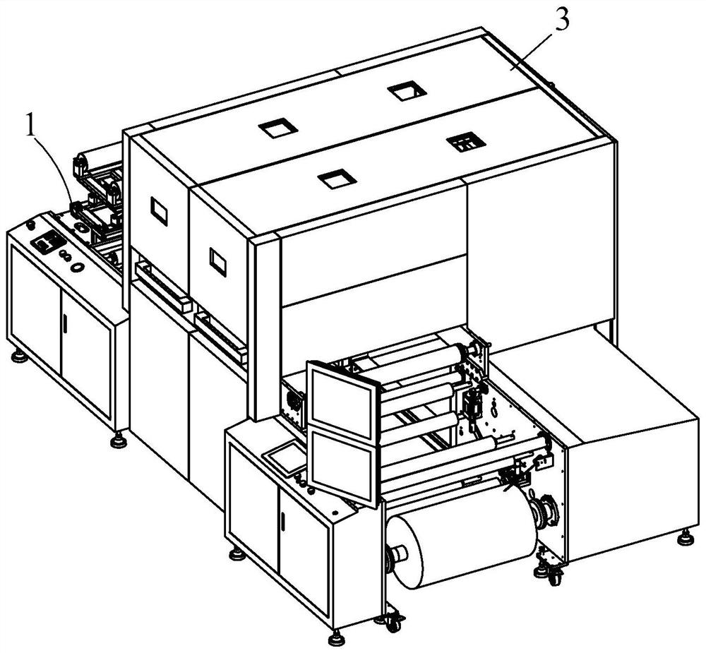
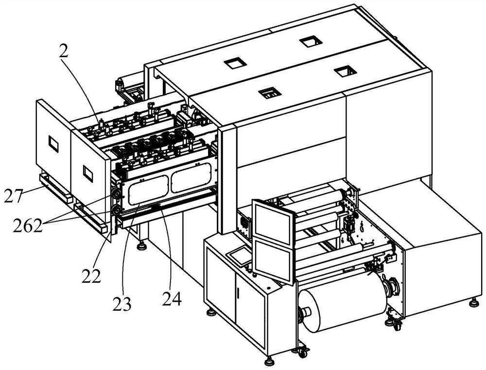
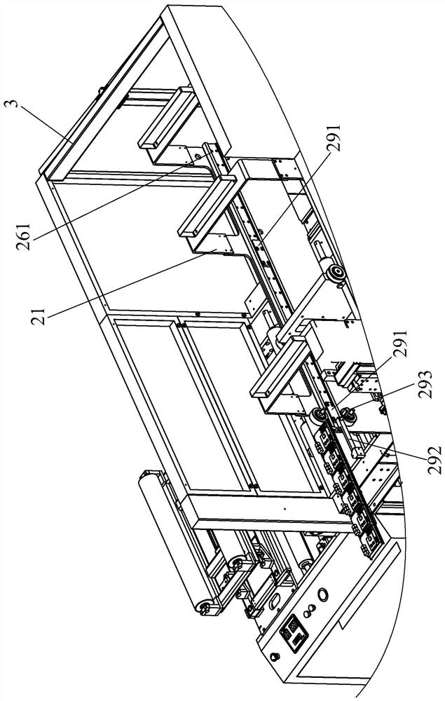
[0063] This embodiment discloses a continuous inkjet printing machine, which includes a frame 1, a printing guide belt and a plurality of push-pull printing systems 2, the printing guide belt is installed on the frame 1, and a plurality of push-pull printing systems 2 are arranged side by side Installed on the frame 1 and located above the printing belt, the push-pull printing system 2 can be integrally pulled out along the direction perpendicular to the printing belt movement direction (see figure 2 ) and advance (see figure 1 ), to facilitate the daily maintenance and inspection of the printing system. Multiple push-pull printing systems 2 are covered and protected with a sheet metal shield 3 .

[0064] In this embodiment, the push-pull printing system 2 includes a gantry frame 21 , an outer frame 22 , a nozzle holder 23 , a multidirectional adjustment mechanism for nozzle groups, a push-pull movement mechanism, a locking positioning...


PUM


Abstract

The invention relates to a push-pull type printing system and a continuous ink-jet printing machine. The push-pull type printing system comprises a gantry frame, an outer frame and a spray head frame provided with a spray head group, the gantry frame is fixedly installed on a machine frame of the continuous ink-jet printing machine and is located above a printing guide belt; the spray head frame is installed in the outer frame in a multi-direction adjustable mode through a spray head set multi-direction adjusting mechanism, the outer frame is movably placed between a pull-out position and a push-in position relative to the gantry frame through a push-pull moving mechanism, part of the outer frame is pulled out of the gantry frame at the pull-out position, and at a push-in position, the part of the outer frame is pushed into the gantry frame. The continuous ink-jet printing machine is provided with the push-pull type printing system. The push-pull type printing system can be integrally pushed in and pulled out, the whole printing system is pulled out when overhaul and daily maintenance are needed, and overhaul work of maintainers is greatly facilitated.

Description

technical field [0001] The invention relates to the technical field of printing machines, in particular to a push-pull printing system and a continuous inkjet printing machine with the push-pull printing system. Background technique [0002] The continuous inkjet printing machine solves the shortcomings of low production efficiency and slow speed of the current scanning digital printing machine. For example, the authorized announcement number is CN205890234U: a continuous high-speed textile digital printing machine. Equivalent to the printing system of this application) is installed on the frame, the two ends of the nozzle assembly are lifting frames, the lifting frame is provided with lifting plates, the lifting plates are installed on the lifting frames on both sides through the lifting guide rails, and the lifting plates are installed with Multiple nozzles and nozzle assemblies are arranged side by side to meet the requirements of fast printing speed, but at present this ...

Claims


Application Information

Patent Timeline
Patent Type & Authority Applications(China)
IPC IPC(8): B41J2/01B41J2/165B41J3/407B41J25/24B41J25/308
CPCB41J2/01B41J2/16552B41J3/4078B41J25/24B41J25/308
Inventor 查银洁潘统明
Owner HANGZHOU HONGHUA DIGITAL TECH
Why Eureka
Try Eureka