
Detection device

A detection device and detection board technology, which is applied in printing devices, printing, etc., can solve problems such as uneven force direction, inability to respond in time, inconsistent detection sensitivity, etc.

Active Publication Date: 2022-05-31
TECO IMAGE SYST
View PDF11 Cites 0 Cited by
  • Summary
  • Abstract
  • Description
  • Claims
  • Application Information

AI Technical Summary

Problems solved by technology

However, due to the uneven force direction of the tension spring on the detection board, the detection board must overcome the initial torsion and static friction when it touches a foreign object, so it cannot respond in time and delays the stop time of the ink car.
Furthermore, in the framework of the tension spring combined with the side of the detection board, since the initial torsion force provided by the tension spring relative to the printing path has directionality, when the detection board performs detection on the back and forth printing path, it is necessary to overcome the different provision. Initial torque, causing inconsistent detection sensitivity

Method used


Image

  • Detection device
  • Detection device
  • Detection device

Examples


Embodiment Construction

[0068] Some typical embodiments embodying the features and advantages of the present invention will be described in detail in the following description. should be understood

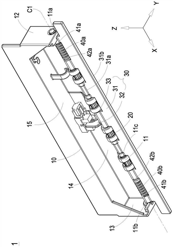
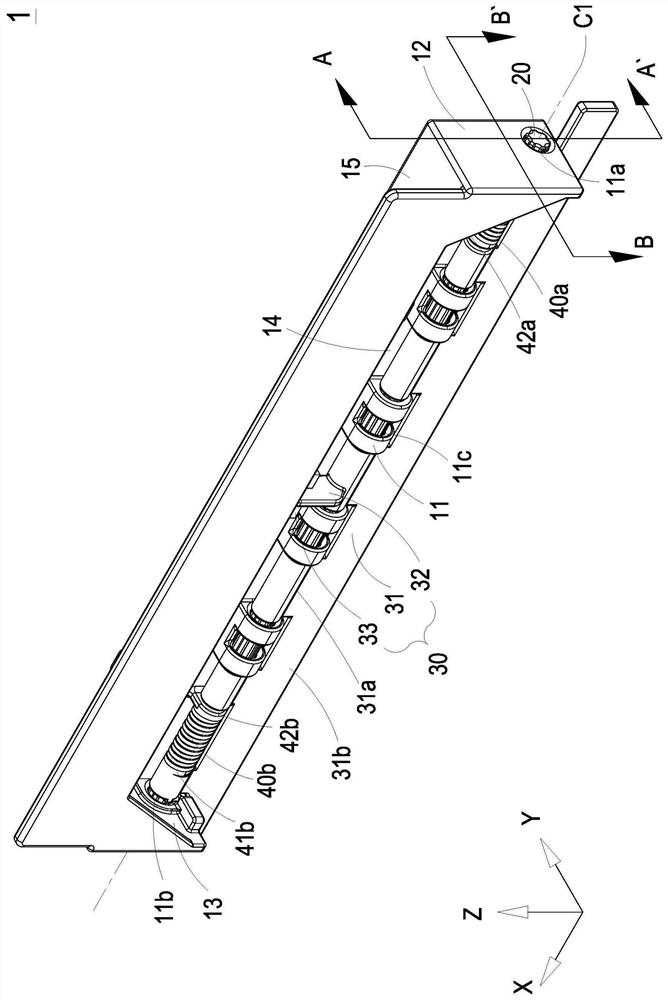
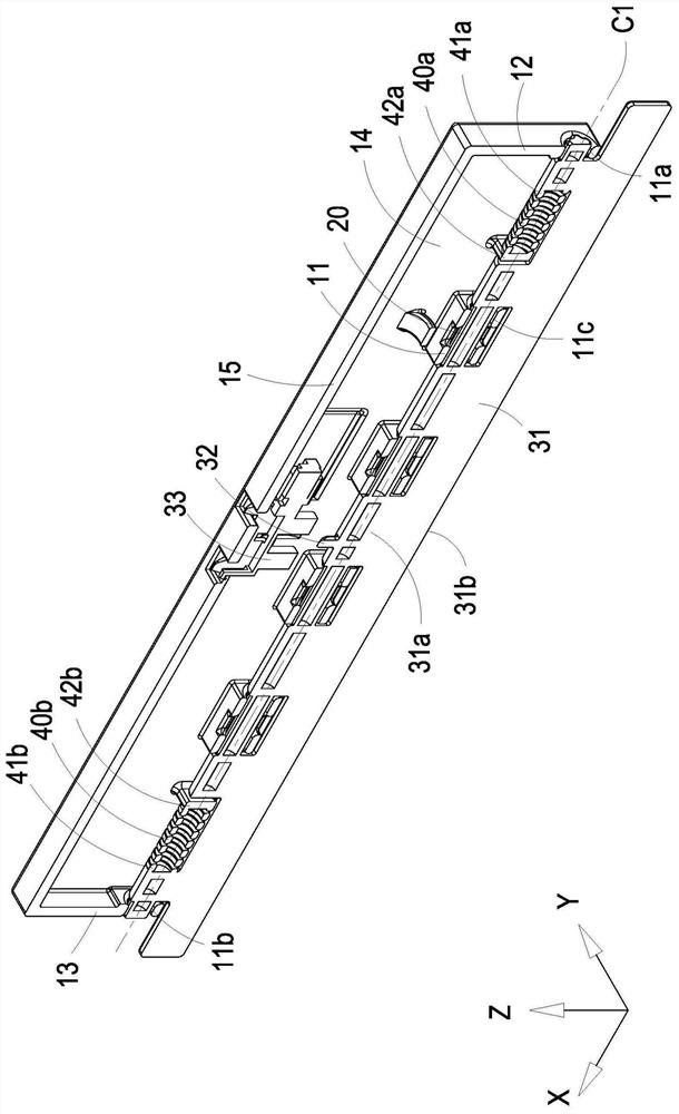
[0069] FIG. 1 discloses a three-dimensional structural diagram of a detection device according to a first embodiment of the present invention. FIG. 2 discloses the first embodiment of the present invention

[0070] FIG. 5 discloses the initial state of the detection device according to the first embodiment of the present invention. FIG. 6 discloses the first embodiment of the present invention.

[0071] FIG. 8 discloses a three-dimensional structural diagram of a detection device according to a second embodiment of the present invention. FIG. 9 shows the second embodiment of the present invention

[0072] FIG. 12 discloses a three-dimensional structural diagram of a detection device according to a third embodiment of the present invention. FIG. 13 discloses the third embodiment of the present invention ...


PUM


Abstract

The invention provides a detection device, which is assembled on the printing path of a printer to detect foreign matter. The detecting device includes a first frame body, a first rotating shaft, two flexible parts and a sensing module. The first rotating shaft is pivotally connected to the first frame body and has a first central axis. The two flexible parts are arranged at two opposite ends of the first rotating shaft along the direction of the first central axis, and are assembled to provide an initial torsion force of the first rotating shaft. Each flexible portion is connected to the first rotating shaft and the first frame. The sensing module includes a detection board with a first side and a second side opposite to each other. The first side is connected to the first rotation axis. When the second side of the detection plate is subjected to force for foreign object detection, the detection plate drives the first rotating shaft, and resists the initial torsion, and rotates around the first central axis, so that the sensing module can detect the first rotating shaft smoothly with the rotation of the detection plate.

Description

Detection device technical field The present invention relates to a kind of detection device, relate in particular to a kind of detection device with concentric elastic structure applied to printer. measuring device. Background technique With the development of inkjet technology, the efficiency of inkjet heads is getting higher and higher, and the moving speed of the ink cart carrying the inkjet head is also increasing. sooner. However, when the ink cart is moving at a high speed, if foreign objects enter the printing path, it is easy to cause a high-speed impact. Otherwise, the machine will be damaged, and it may also cause personal injury. Therefore, the device for detecting foreign objects on the ink car is extremely important. On the other hand, with the development of additive manufacturing technology in recent years, the printing speed The degree of manufacturing has also been greatly improved, enabling mass production of laminate manufacturing, and the limi...

Claims


Application Information

Patent Timeline
Patent Type & Authority Patents(China)
IPC IPC(8): B41J29/393
CPCB41J29/393
Inventor 锺明杰陈鼎钧
Owner TECO IMAGE SYST
Learn More