Urban road drainage device

A technology for drainage devices and roads, applied in water supply devices, drainage structures, waterway systems, etc., can solve problems such as inability to emit in time, increase internal debris, and blockage of drain pipes that cannot be cleaned in time, so as to increase the number of times and improve the efficiency of sound generation , the effect of strengthening the strength

Inactive Publication Date: 2021-06-18
孙梦圆
View PDF1 Cites 0 Cited by
  • Summary
  • Abstract
  • Description
  • Claims
  • Application Information

AI Technical Summary

Problems solved by technology

[0006] Aiming at the deficiencies of the prior art, the present invention provides an urban road drainage device, which solves the problem that the device cannot make a sound in time to notify the staff to dredge the inside of the pipe, and avoids the blockage of the drain pipe that cannot be cleaned in tim

Method used


Image

  • Urban road drainage device
  • Urban road drainage device
  • Urban road drainage device

Examples


Example Embodiment

[0029] Embodiment one

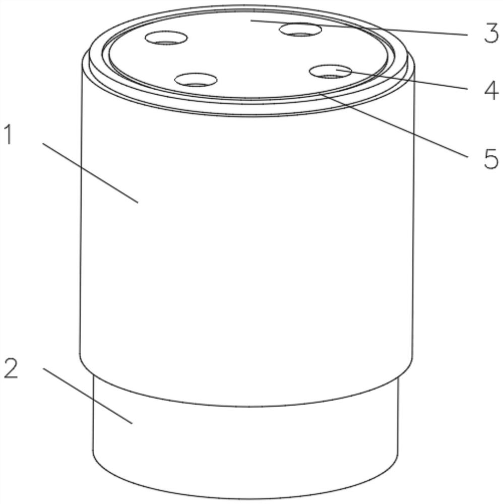
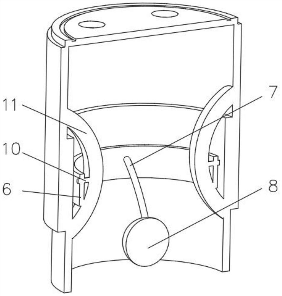
[0030] see Figure 1-3 , the present invention provides a technical solution: an urban road drainage device, comprising a drainage pipe 1, the bottom of the drainage pipe 1 is connected with an extension pipe 2, and the end of the drainage pipe 1 away from the extension pipe 2 is connected with a drainage cover 3, and the drainage cover 3 A water inlet 4 is evenly opened on one side of the drain cover 3, an annular groove 5 is opened on the side away from the drain pipe 1, and an annular block 6 is installed on the inner wall of the extension pipe 2, and the side of the annular block 6 away from the extension pipe 2 is fixedly connected There is a connecting rope 7, and one end of the connecting rope 7 away from the ring block 6 is fixedly connected with a floating device 8, and a spraying device 9 is installed inside the floating device 8.

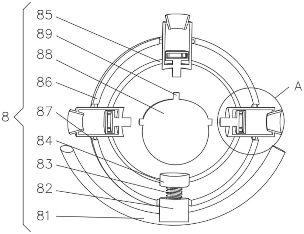
[0031] The floating device 8 includes a floating plate 81, one side of the floating plate 81 is fixedly connect...

Example Embodiment

[0035] Embodiment two

[0036] see Figure 1-4 , the present invention provides a technical solution: on the basis of Embodiment 1, the spraying device 9 includes a device frame 91, lime powder is housed inside the device frame 91, and elastic rods 92 are symmetrically installed on one side of the device frame 91, and the elastic rods 92 is fixedly connected with circular hole 87 at one end away from device frame 91, and the inside of device frame 91 is equipped with push rod 93, and one end of push rod 93 runs through device frame 91, and one end of push rod 93 is fixedly connected with push plate 94, and device frame The side of 91 away from the push rod 93 communicates with a discharge port 95 .

[0037]During use, the circular push block 84 is subjected to buoyancy to squeeze the elastic air bag 88 inwardly, pushes the push rod 89 to squeeze the push rod 93, and the push rod 93 pushes the push plate 94 to remove the lime powder inside the device frame 91 from the discharg...

Example Embodiment

[0038] Embodiment three

[0039] see Figure 1-5 , the present invention provides a technical solution: on the basis of Embodiment 2, a connecting block 10 is fixedly connected to the side of the ring block 6 close to the connecting rope 7, and a shaking device 11 is installed on the side of the connecting block 10 away from the ring block 6, The shaking device 11 includes a shaking plate 111, one side of the shaking plate 111 is fixedly connected with the inner wall of the drain pipe 1, and the side of the shaking plate 111 away from the drain pipe 1 is uniformly provided with a circular groove 112, and one side of the circular groove 112 is installed with Elastic arc plate 113 , a gravity ball 114 is installed on the side of elastic arc plate 113 away from circular groove 112 .

[0040] A second spring 115 is fixedly connected to one side of the circular groove 112 , and an end of the second spring 115 away from the circular groove 112 is fixedly connected to the elastic ar...


PUM


Abstract

The invention discloses an urban road drainage device. The urban road drainage device comprises a drainage pipe, the bottom of the drainage pipe communicates with an extension pipe, the end, away from the extension pipe, of the drainage pipe is connected with a drainage cover, water inlet holes are evenly formed in one side of the drainage cover, and an annular groove is formed in the side, away from the drainage pipe, of the drainage cover; an annular block is installed on the inner wall of the extension pipe, a connecting rope is fixedly connected to the side, away from the extension pipe, of the annular block, a floating device is fixedly connected to the end, away from the annular block, of the connecting rope, a spraying device is installed in the floating device, a connecting block is fixedly connected to the side, close to the connecting rope, of the annular block, and a shaking device is installed on the side, away from the annular block, of the connecting block. The invention relates to the technical field of drainage. According to the urban road drainage device, the device can make a sound in time so as to inform a worker to dredge the interior of the pipe, and the problem that too much water is accumulated on the road surface due to the fact that the drainage pipe is blocked and cannot be cleaned in time is solved.

Description

technical field [0001] The invention relates to the technical field of drainage, in particular to an urban road drainage device. Background technique [0002] Urban road drainage refers to the measures taken to eliminate the precipitation on the urban road surface. Usually, the road surface water flows into the street ditch according to the slope of the road surface, and then flows into the connecting pipe from the street ditch through the rainwater outlet, and the connecting pipe enters the people through the inspection well. The main drainage pipe is then discharged from the outlet of the main drainage pipe to nearby rivers, lakes, seas and other water bodies. [0003] For example, Chinese patent CN111851286A proposes a drainage pipe with anti-clogging function for road bridges, including a first pipe, a second pipe, a well cover, a fixing block and teeth, and the left surface of the first pipe is fixedly connected with a second pipe. pipeline, and both the second pipelin...

Claims


Application Information

Patent Timeline
IPC IPC(8): E03F5/04E03F5/06E03F7/00A61L11/00A61L2/23A61L2/26A61L101/02
CPCA61L2/23A61L2/26A61L11/00E03F5/0401E03F5/06E03F7/00
Inventor 孙梦圆
Owner 孙梦圆
Why Eureka
Try Eureka