High-temperature-resistant detection device for wave-absorbing composite material

A composite material and detection device technology, applied in measurement devices, analytical materials, material thermal analysis and other directions, can solve problems such as inconvenient heating angle adjustment, inability to meet usage requirements, and inability to transfer heat and heat preservation, so as to facilitate detection work, The effect of increasing uniformity and reducing contact area

Pending Publication Date: 2021-06-18
黄江
View PDF7 Cites 0 Cited by
  • Summary
  • Abstract
  • Description
  • Claims
  • Application Information

AI Technical Summary

Problems solved by technology

[0003] At present, the high-temperature reflectivity test system mainly adopts the method of bottom heating, that is, the heating element is arranged under the sample to be tested, and the radar wave incident surface is the upper surface. When testing the high-temperature reflectivity of the sample to be tested, the hot surface and the radar wave incident surface are not On the same side, it is inconvenient to adjust the heating angle, and it is impossible to carry out heat preservation and transfer work during the heating process, resulting in a large amount of heat loss, which cannot meet the needs of use

Method used


Image

  • High-temperature-resistant detection device for wave-absorbing composite material
  • High-temperature-resistant detection device for wave-absorbing composite material
  • High-temperature-resistant detection device for wave-absorbing composite material

Examples


Embodiment Construction

[0024] The following will clearly and completely describe the technical solutions in the embodiments of the present invention with reference to the accompanying drawings in the embodiments of the present invention. Obviously, the described embodiments are only some, not all, embodiments of the present invention.

[0025] Examples of the described embodiments are shown in the drawings, wherein like or similar reference numerals designate like or similar elements or elements having the same or similar functions throughout. The embodiments described below by referring to the figures are exemplary and are only used for explaining the patent, and should not be construed as limiting the patent.

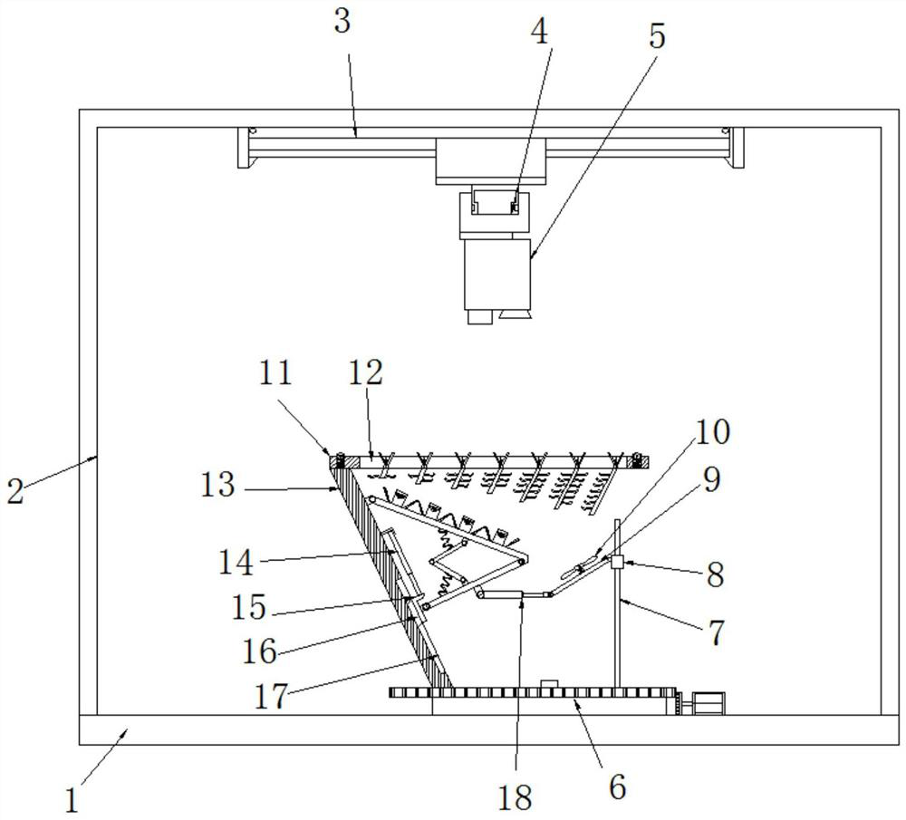
[0026] refer to Figure 1-4 , a high-temperature-resistant detection device for wave-absorbing composite materials, including a bottom plate 1, a detection box 2 is fixed on the top of the bottom plate 1, a through-beam antenna 5 is provided on the inner wall of the top of the detection box...


PUM


Abstract

The invention discloses a high-temperature-resistant detection device for a wave-absorbing composite material, which comprises a bottom plate, wherein a detection box body is fixed to the top of the bottom plate, a correlation antenna is arranged on the inner wall of the top of the detection box body, a rotating disc is rotationally installed in the center of the inner wall of the top of the bottom plate, a supporting plate is fixed to one side of the top of the rotating disc, a sample plate placement plate is fixed to the top end of the supporting plate, a heating mechanism is rotatably installed at the top end of the supporting plate, a bending plate is rotatably installed at the bottom end of the heating mechanism, a reset mechanism is rotatably installed between the bending plate and the heating mechanism, a telescopic mechanism is fixed to the supporting plate, the bottom end of the telescopic mechanism is rotatably connected with the bending plate, a heat conduction opening is formed in the top of the sample plate placement plate, a plurality of inclined heat conduction mechanisms distributed at equal intervals are fixed in the heat conduction opening, and the lengths of the heat conduction mechanisms are gradually increased from left to right. The heating mechanism can be adjusted, and heat in the heating process can be insulated and transferred.

Description

technical field [0001] The invention relates to the technical field of microwave testing equipment, in particular to a high-temperature-resistant detection device for microwave-absorbing composite materials. Background technique [0002] Radar absorbing materials (referred to as absorbing materials) are widely used in civil and military fields, and radar reflectivity (referred to as reflectivity) is an important index parameter used to evaluate the absorbing performance of absorbing materials. The reflectivity measurement technology of absorbing materials at room temperature is relatively mature and has been widely used. However, as engines, high-speed aircraft and high-power microwave devices increase the temperature resistance of absorbing materials, radar The requirements of the reflectivity test system are also getting higher and higher. [0003] At present, the high-temperature reflectivity test system mainly adopts the method of bottom heating, that is, the heating el...

Claims


Application Information

Patent Timeline
Patent Type & Authority Applications(China)
IPC IPC(8): G01N25/00
CPCG01N25/00
Inventor 黄江
Owner 黄江
Why Eureka
Try Eureka