
Transformer equipment with self-checking function

A technology for transformers and transformer oil, applied in the field of transformers, can solve the problems of transformer structural damage, decreased insulation effect, transformer oil pollution, etc., and achieves the effects of speeding up the flow, reducing the probability of explosion, and improving the cooling work.

Inactive Publication Date: 2021-06-18
佛山市环屋家具有限公司
View PDF0 Cites 0 Cited by
  • Summary
  • Abstract
  • Description
  • Claims
  • Application Information

AI Technical Summary

Problems solved by technology

[0002] A transformer is a power device that uses the principle of electromagnetic induction to convert alternating current energy into different voltages and currents. In order to ensure the working environment of the windings in the transformer, the windings are usually immersed in an oil tank filled with transformer oil. The transformer oil can play a role in the winding. Strengthen the function of insulation and cooling and heat dissipation, and when the transformer is overloaded, short-circuited and other faults, the winding will generate a high-temperature arc to thermally decompose the insulating oil, so that the transformer structure will be damaged, or even explode. When the winding is short-circuited, due to Occurs internally and is not easy to be seen. When a fault occurs, the best time for maintenance is mostly missed. At the same time, after the winding arcs, it will pollute the surrounding transformer oil, thereby reducing its insulation effect. A transformer device with a self-checking function described in the invention can solve the above problems

Method used


Image

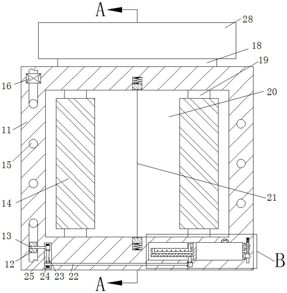
  • Transformer equipment with self-checking function
  • Transformer equipment with self-checking function
  • Transformer equipment with self-checking function

Examples


Embodiment Construction

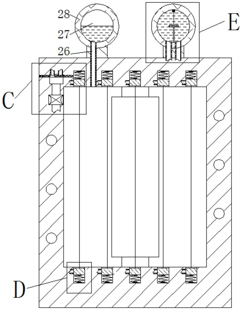
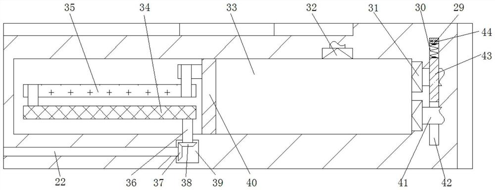
[0019] Combine below Figure 1-6 The present invention is described in detail, wherein, for the convenience of description, the orientations mentioned below are defined as follows: figure 1 The up, down, left, right, front and back directions of the projection relationship itself are the same.

[0020]According to the present invention, a transformer device with a self-test function includes a main body 11, a winding cavity 20 is provided in the main body 11, and the winding cavity 20 is filled with transformer oil. The upper and lower sides of the winding cavity 20 A left-right symmetrical winding core 19 is fixed between the walls, and windings 14 are respectively fixed on the outer circular surfaces of the winding core 19 on the left and right sides. The closed block cavity 61, the closed block cavity 61 on the upper and lower sides is respectively provided with a closed block 62 that can slide up and down, and a fuse rope 21 is fixedly connected between the corresponding ...


PUM


Abstract

Transformer equipment with a self-checking function disclosed by the present invention comprises a main body. A winding cavity is arranged in the main body, the winding cavity is filled with transformer oil, winding cores in bilateral symmetry are fixedly arranged between the upper wall and the lower wall in the winding cavity, and windings are fixedly arranged on the outer circular surfaces of the winding cores on the left side and the right side respectively. Closed block cavities which are symmetrical to each other and are uniformly distributed are arranged between the upper wall and the lower wall in the winding cavity in a communicating manner. According to the invention, after an electric arc is in contact with fusing ropes, the flowing of transformer oil in the winding cavity is accelerated so that the winding is better cooled, then the phenomenon of fusing occurs through a plurality of fusing ropes 21, clean transformer oil is driven to enter the winding cavity, the original transformer oil in the winding cavity is replaced, the working environment of the winding is guaranteed, the arc generation probability of the winding is further reduced, and meanwhile a main body explosion probability is also decreased.

Description

technical field [0001] The invention relates to the technical field of transformers, in particular to transformer equipment with a self-checking function. Background technique [0002] A transformer is a power device that uses the principle of electromagnetic induction to convert alternating current energy into different voltages and currents. In order to ensure the working environment of the windings in the transformer, the windings are usually immersed in an oil tank filled with transformer oil. The transformer oil can play a role in the winding. Strengthen the function of insulation and cooling and heat dissipation, and when the transformer is overloaded, short-circuited and other faults, the winding will generate a high-temperature arc to thermally decompose the insulating oil, so that the transformer structure will be damaged, or even explode. When the winding is short-circuited, due to Occurs internally and is not easy to be seen. When a fault occurs, the best time for...

Claims


Application Information

Patent Timeline
Patent Type & Authority Applications(China)
IPC IPC(8): H01F27/14H01F27/28
CPCH01F27/14H01F27/2876
Inventor 吴丽谷
Owner 佛山市环屋家具有限公司
Learn More