Check patentability & draft patents in minutes with Patsnap Eureka AI!

Motor bearing cooling structure

A technology of cooling structure and motor bearing, applied in the direction of cooling/ventilation device, casing/housing/support, electrical components, etc., can solve the problems of high rotor speed, affecting bearing lubrication performance, bearing temperature rise, etc.

Active Publication Date: 2021-06-18
CRRC YONGJI ELECTRIC CO LTD
View PDF7 Cites 1 Cited by
  • Summary
  • Abstract
  • Description
  • Claims
  • Application Information

AI Technical Summary

Problems solved by technology

[0005] The embodiment of the present invention provides a motor bearing cooling structure, which is used to solve the technical problem in the prior art that the rotor rotates at a high speed during the operation of the motor, which causes the temperature of the bearing to rise, thereby affecting the lubrication performance of the bearing.

Method used


Image

  • Motor bearing cooling structure
  • Motor bearing cooling structure
  • Motor bearing cooling structure

Examples


Embodiment Construction

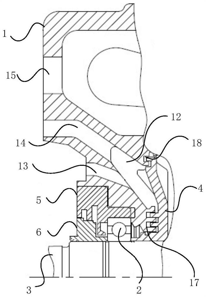
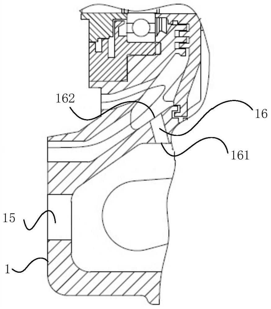
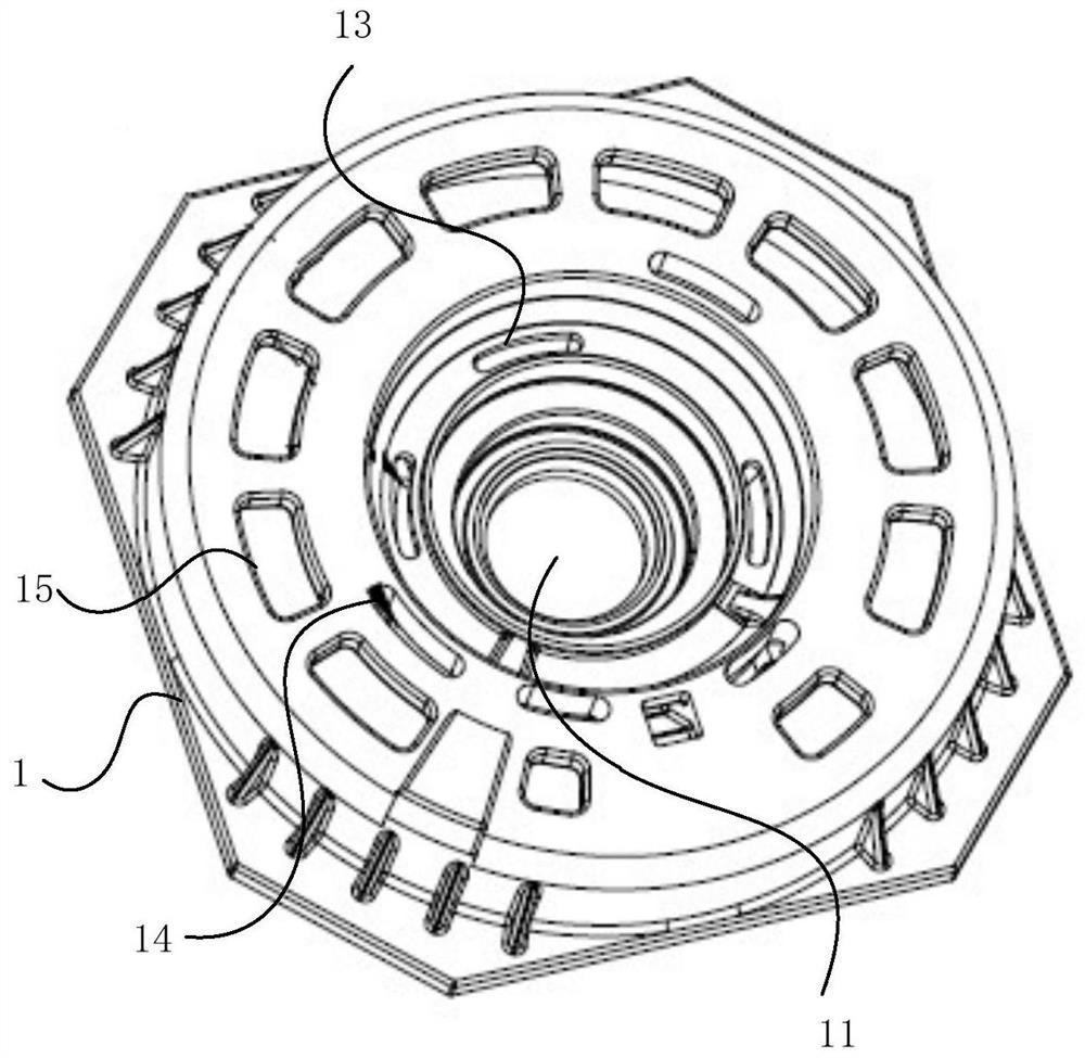
[0043] In order to make the purpose, technical solutions and advantages of the embodiments of the present invention clearer, the technical solutions in the embodiments of the present invention will be clearly and completely described below in conjunction with the drawings in the embodiments of the present invention. Obviously, the described embodiments It is a part of embodiments of the present invention, but not all embodiments. Based on the embodiments of the present invention, all other embodiments obtained by persons of ordinary skill in the art without making creative efforts belong to the protection scope of the present invention. In the case of no conflict, the following embodiments and features in the embodiments can be combined with each other.

[0044] In the present invention, unless otherwise specified, the terms "installation", "connection", "connection", "fixation" and other terms should be understood in a broad sense, for example, it can be a fixed connection or...


PUM


Abstract

The embodiment of the invention provides a motor bearing cooling structure. The motor bearing cooling structure comprises an end cover, a bearing, a main shaft and an inner sealing ring. First centrifugal fan blades are arranged on the inner sealing ring, a cavity used for containing the first centrifugal fan blades is formed in the inner wall of the end cover, an air outlet channel and an air inlet channel which extend to the cavity are formed in the outer wall of the end cover; the air outlet channel, the air inlet channel and the cavity jointly form a bearing cooling air channel; and the air inlet channel is arranged close to the shaft hole, so that the bearing cooling air channel is close to the bearing. The inner sealing ring is in transmission connection with the main shaft, when the main shaft rotates, the inner sealing ring is driven to rotate, the first centrifugal fan blades on the inner sealing ring drive air to enter the cavity from the air inlet channel, and the air in the cavity flows out from the air outlet channel; and the air inlet channel is arranged close to the shaft hole, and in the air circulating process, the air in the air inlet channel exchanges heat with the side wall of the shaft hole, so that heat dissipation of the end cover near the shaft hole is achieved, cooling of the bearing is achieved, and the situation that the lubricating performance is affected due to the fact that the temperature of the bearing is too high is avoided.

Description

technical field [0001] The invention relates to the technical field of motors, in particular to a cooling structure for motor bearings. Background technique [0002] Motors are commonly used in rail trains, automobiles and other equipment as a power source. The motor includes a housing, a stator and a rotor. The stator is arranged on the inner wall of the housing, and the stator is surrounded by a rotating cavity. The rotor is arranged in the rotating cavity. The rotor One end has a main shaft protruding outside the housing. [0003] In the related art, the housing includes end caps for blocking the two ends of the rotating cavity, the end caps are provided with shaft holes, the main shaft protrudes from the shaft holes to the outside of the housing, and a bearing is provided between the main shaft and the shaft holes to realize The main shaft rotates at high speed in the shaft hole of the end cover. [0004] During the working process of the motor, the rotor speed is high...

Claims


Application Information

Patent Timeline
Patent Type & Authority Applications(China)
IPC IPC(8): H02K5/20H02K5/16H02K9/06
CPCH02K5/20H02K5/16H02K9/06
Inventor 李广贾喜勤张婷许勇刘永强张伟姬春霞
Owner CRRC YONGJI ELECTRIC CO LTD
Features
  • R&D
  • Intellectual Property
  • Life Sciences
  • Materials
  • Tech Scout
  • Unparalleled Data Quality
  • Higher Quality Content
  • 60% Fewer Hallucinations
Learn More