
Monitoring equipment convenient to overhaul and used for storage

A technology for monitoring equipment and warehousing, applied in the field of monitoring equipment, can solve problems such as blurred vision, potential safety hazards, loss of position, etc., and achieve the effect of improving work efficiency, avoiding dangerous accidents, and reducing position height

Pending Publication Date: 2021-06-18
徐晓宁
View PDF0 Cites 0 Cited by
  • Summary
  • Abstract
  • Description
  • Claims
  • Application Information

AI Technical Summary

Problems solved by technology

[0004] 1. The existing monitoring equipment for warehousing usually needs to be installed at a position high from the ground when used in a large warehouse, which will cause trouble for the inspection and maintenance of the monitoring equipment. The maintenance personnel need to use a ladder to ascend to the same level as Maintenance should be carried out at the same height as the monitoring equipment, which will cause potential safety hazards
[0005] 2. Workers generate dust when they are working in the warehouse, and the dust will float to the sky, and finally fall down slowly. However, the monitoring equipment installed at a high distance from the ground will fall on the dust immediately, and the long-term dust fall will make the The lens of the monitoring equipment is blocked by dust, resulting in blurred vision and affecting the normal use of the monitoring equipment
[0006] 3. The existing monitoring equipment for warehousing does not have an alarm and positioning function. When an intrusion is found, the on-duty personnel cannot be effectively reminded to pay attention, which delays the most effective investigation period and causes the loss of location.

Method used


Image

  • Monitoring equipment convenient to overhaul and used for storage
  • Monitoring equipment convenient to overhaul and used for storage
  • Monitoring equipment convenient to overhaul and used for storage

Examples


Embodiment Construction

[0023] The following will clearly and completely describe the technical solutions in the embodiments of the present invention with reference to the accompanying drawings in the embodiments of the present invention. Obviously, the described embodiments are only some, not all, embodiments of the present invention. Based on the embodiments of the present invention, all other embodiments obtained by persons of ordinary skill in the art without making creative efforts belong to the protection scope of the present invention.

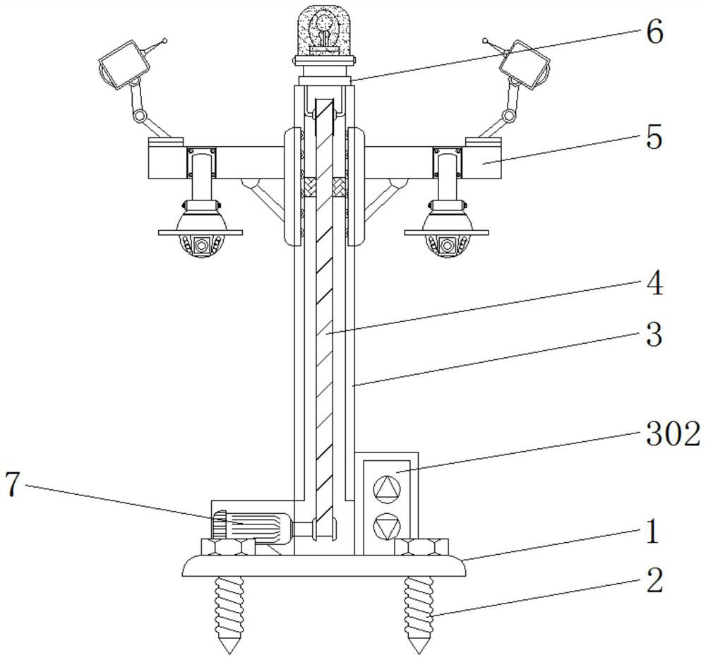
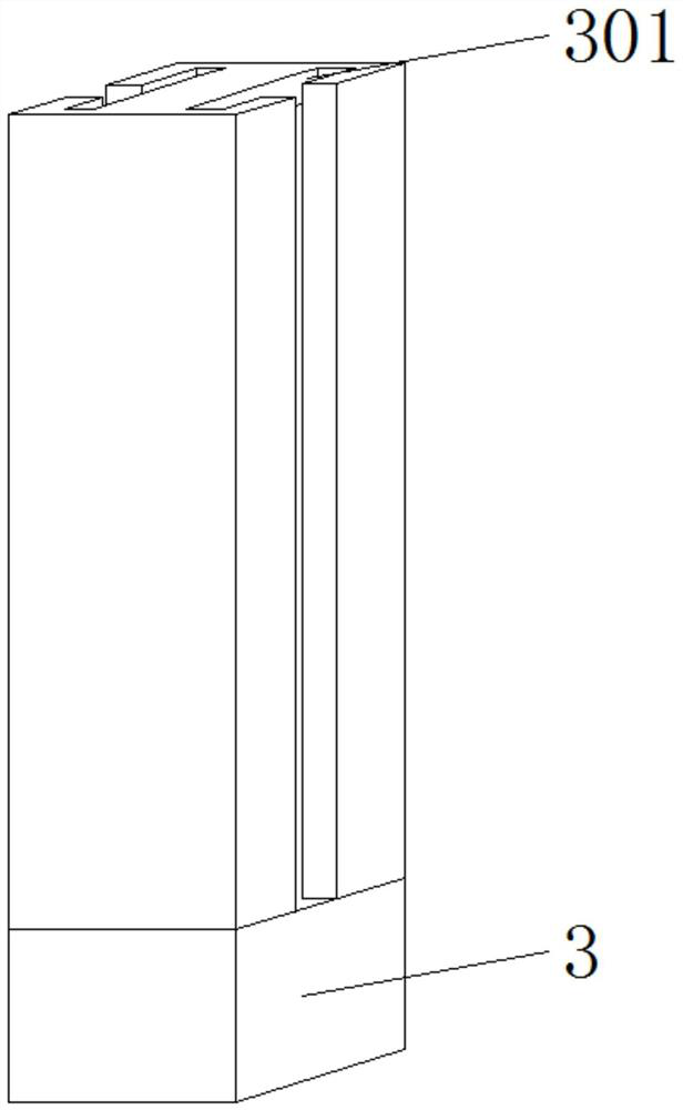
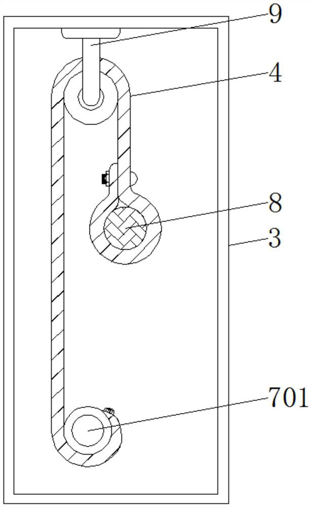
[0024] see Figure 1-5 , an embodiment provided by the present invention: a convenient maintenance monitoring device for warehousing, including a mounting base plate 1, a main rod 3, a fixing frame 5 and an alarm 6, and a threaded mounting nail 2 is installed through the mounting base plate 1, The whole device can be fixed on the ground by threaded mounting nails 2, the main rod 3 and the rotating motor 7 are welded on the top of the installation base plate 1,...


PUM


Abstract

The invention discloses monitoring equipment convenient to overhaul and used for storage, and the monitoring equipment comprises a mounting bottom plate, a main rod, a fixed frame and an alarm; a threaded mounting nail is mounted on the mounting bottom plate in a penetrating mode, the main rod and a rotating motor are welded to the upper portion of the mounting bottom plate, and the output end of the rotating motor is fixed to the interior of the main rod in a penetrating mode; the fixing frames are movably installed in the main rod, the transmission belt is installed in the main rod, one end of the transmission belt is installed at the output end of the rotating motor through a screw, the other end of the transmission belt is installed on a connecting rod between the fixing frames, and the alarm is installed at the top of the main rod through a screw. According to the monitoring equipment, the dust cover is installed on the monitoring equipment, the dust cover can prevent dust from directly falling on a lens of the monitoring equipment, the situation that a rear-end pan-tilt displayer is fuzzy and the monitoring equipment cannot be used normally is avoided, and the working efficiency of the monitoring equipment is improved.

Description

technical field [0001] The invention relates to the technical field of monitoring equipment, in particular to monitoring equipment for easy maintenance of storage. Background technique [0002] Monitoring equipment refers to a series of monitoring equipment invented for continuous attention to behavior and activities or other changing information, usually for the purpose of influencing, managing, guiding or protecting people. A typical TV monitoring system is mainly composed of front-end equipment and back-end equipment. For some large warehouses, the use of monitoring equipment is essential. [0003] The defective that exists in existing technology is: [0004] 1. The existing monitoring equipment for warehousing usually needs to be installed at a position high from the ground when used in a large warehouse, which will cause trouble for the inspection and maintenance of the monitoring equipment. The maintenance personnel need to use a ladder to ascend to the same level as ...

Claims


Application Information

Patent Timeline
Patent Type & Authority Applications(China)
IPC IPC(8): H04N5/225F16M11/04F16M11/18G08B3/10G08B5/38
CPCG08B3/10G08B5/38F16M11/04F16M11/18H04N23/51
Inventor 徐晓宁
Owner 徐晓宁
Learn More