Electric motor

An electric motor and motor technology, applied in the direction of electric components, electromechanical devices, electrical components, etc., can solve problems such as motor and electronic device damage

Pending Publication Date: 2021-06-18
KSB AG
View PDF3 Cites 0 Cited by
  • Summary
  • Abstract
  • Description
  • Claims
  • Application Information

AI Technical Summary

Problems solved by technology

Inadmissibly high heat generation can cause damage to motors and electronics

Method used


Image

  • Electric motor
  • Electric motor
  • Electric motor

Examples


Embodiment Construction

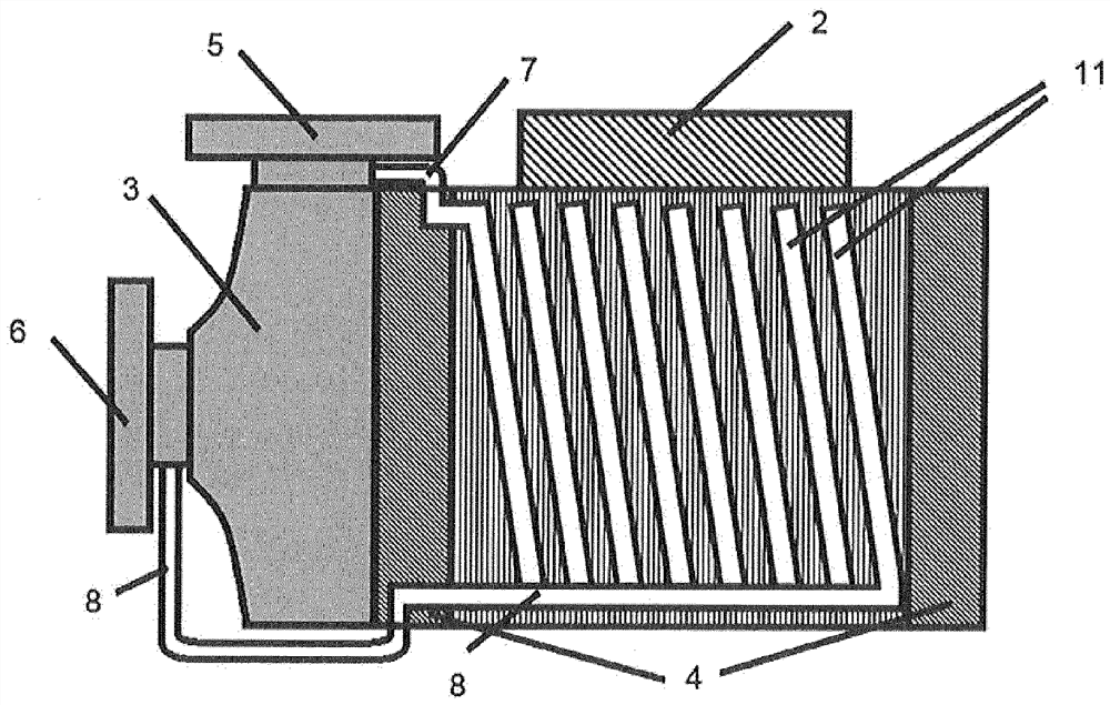
[0024] figure 1 An electrically driven pump is shown, which is equipped with an electric motor 1 and power electronics 2 . The pump can be, for example, a centrifugal pump, wherein other pump types are also possible. The shown pump has a pump housing 3 which is flanged to one of the bearing shields 4 of the electric motor. Furthermore, connections for the fluid lines are provided on the pump housing 3 , one connection each for the pressure side 5 and the suction side 6 . The inlet line 7 and the return line 8 of the cooling system are arranged at these connections. Thus, cold conveying fluid is fed into the coolant channels on the pressure side 5 and then fed into the conveying fluid flow on the suction side 6 again. The supply line 7 and the return line 8 of the cooling system can be located both inside and outside the pump housing.

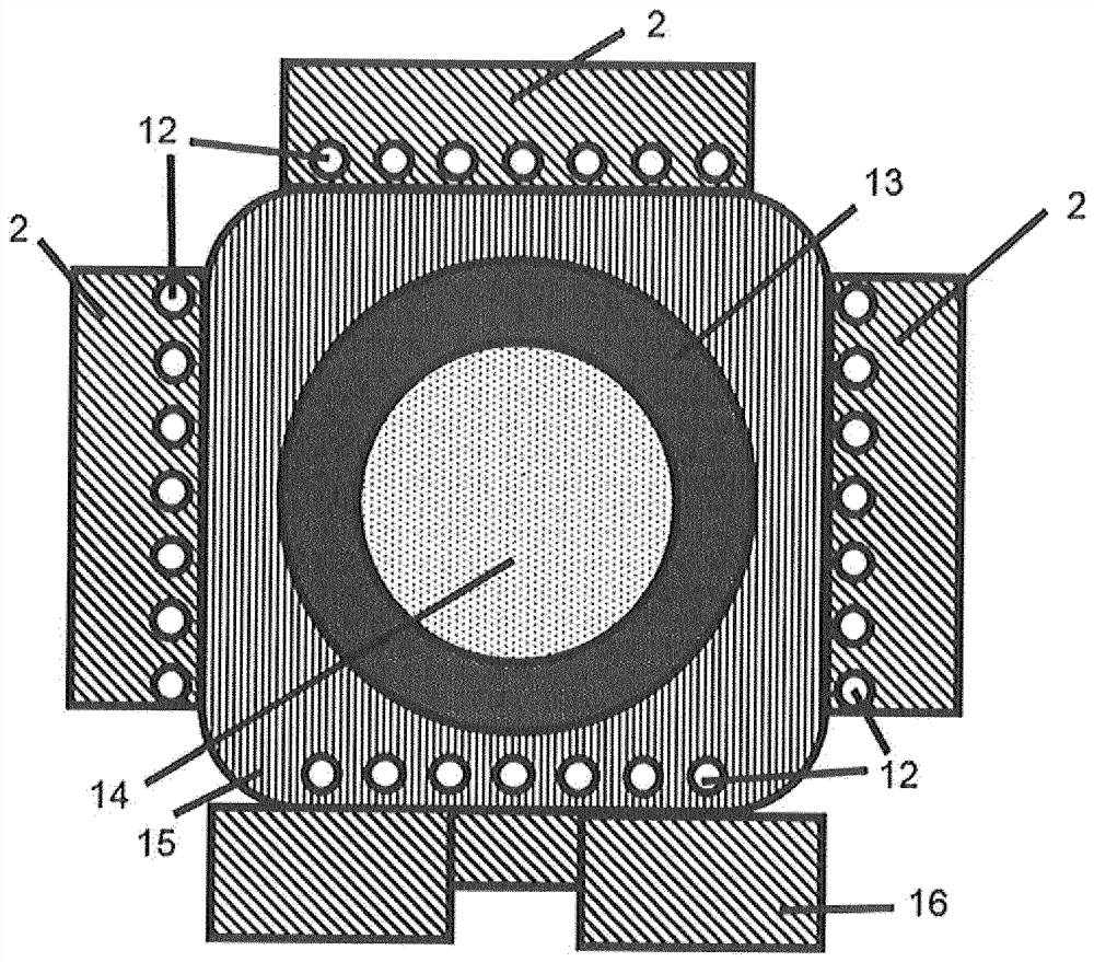
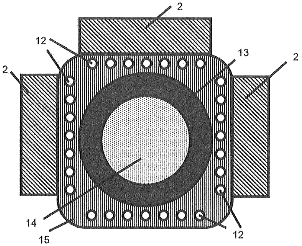
[0025] figure 2 An axial illustration of a pump according to the invention is shown with a helical coolant channel 11 which is directly c...


PUM


Abstract

The invention relates to an electric motor having a connected power electronics and a pump, comprising a pump chamber having a suction-side and a pressure-side connection, wherein a cooling device of the power electronics and / or of the motor is connected to the pump chamber.

Description

technical field [0001] The invention relates to an electric motor connected to a pump and electronic components. Background technique [0002] In the electric motor and the associated power electronics, more or less losses are generated during continuous operation and heat is released as a result of the load. Inadmissibly high heat generation can result in damage to the motor and electronics. In order to increase the power density of a drive, designers of regulated drives often seek suitable measures for dissipating heat from the drive. [0003] US 2005 0047 933 A1 describes a motor pump in which the conveying medium is guided through a multi-walled pump housing. [0004] WO 2015 / 195 411 A1 describes an arrangement of the power electronics in a pump housing, which is intended to be used for cooling by a conveying medium. [0005] JP 2007 211 695 A describes the cooling of a cooling body which absorbs the heat of the power electronics and cools it with a conveying medium. ...

Claims


Application Information

Patent Timeline
Patent Type & Authority Applications(China)
IPC IPC(8): H02K5/20F04D13/06F04D29/58H02K9/19H02K11/33
CPCF04D29/5806F04D29/5813F04D13/06H02K11/33H02K5/203H02K9/225H02K5/15H02K9/193H02K9/20
Inventor B·扬吉克
Owner KSB AG
Why Eureka
Try Eureka