Electric spindle assembly with hydraulic cylinder and center cooling function

A technology of hydraulic cylinders and electric spindles, applied in maintenance and safety accessories, manufacturing tools, metal processing equipment, etc., can solve the problems of short service life of electric spindles, decline in overall performance of spindles, and inability to cool electric spindles, so as to reduce friction, Integrated compact structure and improved cooling efficiency

Active Publication Date: 2021-06-22
宁波天控五轴数控技术有限公司
View PDF5 Cites 1 Cited by
  • Summary
  • Abstract
  • Description
  • Claims
  • Application Information

AI Technical Summary

Problems solved by technology

[0002] In the prior art, the hydraulic device for controlling the pull rod of the electric spindle and the cooling device for the electric spindle are complex in structure, and are assembled with the electric spindle separately, which takes up a large space and is inconvenient to install; at the same time, the cooling device for the electric spindle can only cool the shell of the spindle and cannot The internal cooling of the high-speed rotating electric spindle leads to a large internal temperature rise when the electric spindle is operating at high speed, which reduces the overall performance of the spindle and shortens the service life of the electric spindle

Method used


Image

  • Electric spindle assembly with hydraulic cylinder and center cooling function
  • Electric spindle assembly with hydraulic cylinder and center cooling function
  • Electric spindle assembly with hydraulic cylinder and center cooling function

Examples


Embodiment Construction

[0027] The following will clearly and completely describe the technical solutions in the embodiments of the present invention with reference to the accompanying drawings in the embodiments of the present invention. Obviously, the described embodiments are only some, not all, embodiments of the present invention. Based on the embodiments of the present invention, all other embodiments obtained by persons of ordinary skill in the art without making creative efforts belong to the protection scope of the present invention.

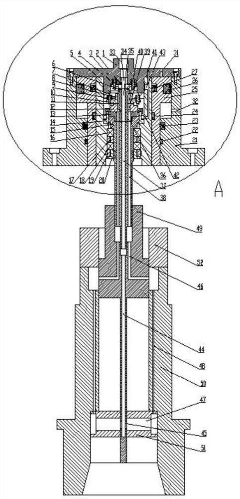
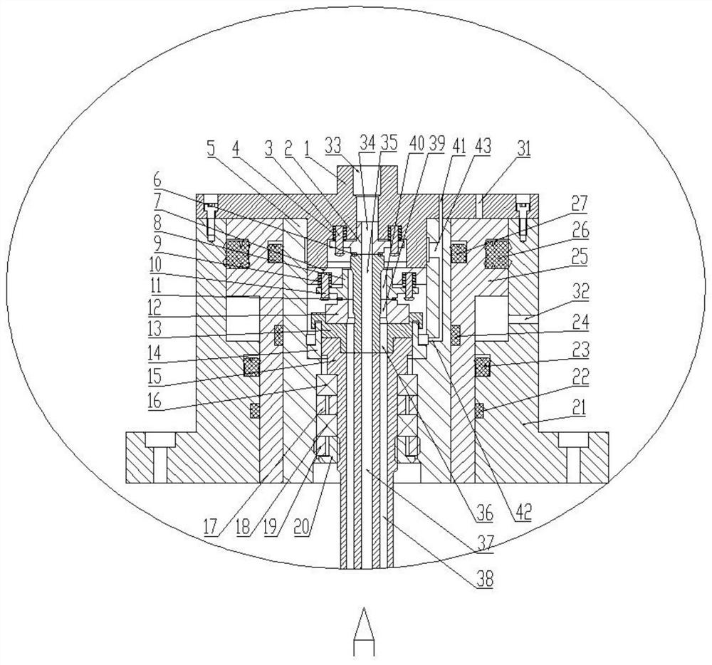
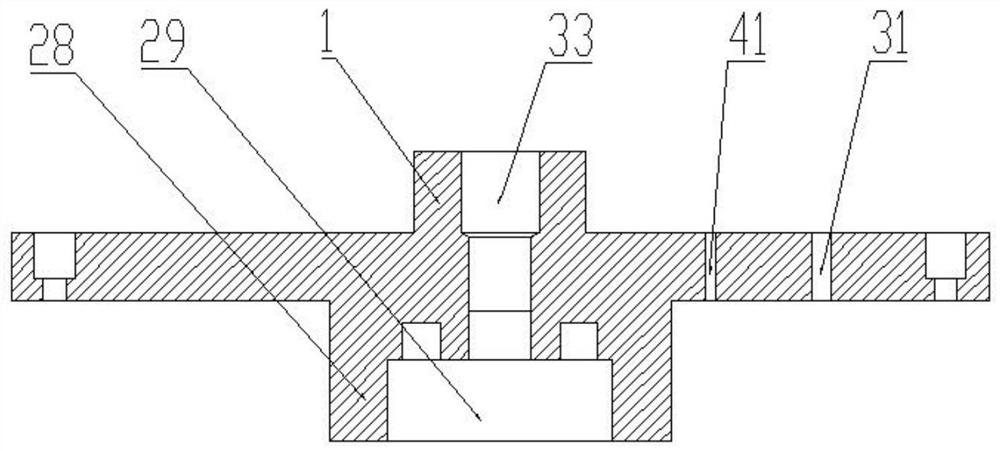
[0028] see Figure 1-7, the embodiment of the present invention discloses an electric spindle assembly with hydraulic cylinder and central cooling, including: end cover 1, inner casing 5, outer casing 21, hydraulic cylinder piston 25, top end gland 2, sealing disc 7. Limiting sleeve 8, spacer sleeve 12, rotating connector 13, support ring 14 and rotating shaft 15, one end of end cover 1 has a raised portion 28, the end surface of raised portion 28 has a concav...


PUM


Abstract

The invention discloses an electric spindle assembly with a hydraulic cylinder and a center cooling function. The electric spindle assembly comprises a first channel arranged on an end cover and communicating with a containing cavity, a second channel is arranged on an outer shell and communicates with the containing cavity, and a piston of the hydraulic cylinder can move along the axial direction of an inner shell by introducing hydraulic oil from the first channel or the second channel. A third channel communicates with a fourth channel, a fifth channel and a seventh channel in sequence to form a liquid inlet channel, an eighth channel communicates with a sixth channel, a ninth channel and a tenth channel in sequence to form a liquid outlet channel, and a twelfth channel communicates with the liquid outlet channel through an abutting gap between a limiting sleeve and a spacer bush; and a thirteenth channel communicates with the liquid inlet channel through a gap between a raised shaft and a top end gland. The hydraulic cylinder piston for controlling a broach device and a center cooling structure for cooling the interior of the electric spindle are combined together, so that the integrated structure is more compact, cooling liquid can enter through a single channel and exit through multiple channels, and then the cooling efficiency is improved.

Description

technical field [0001] The invention relates to the technical field of electric spindles, in particular to an assembly for electric spindles with hydraulic cylinders and central cooling. Background technique [0002] In the prior art, the hydraulic device for controlling the pull rod of the electric spindle and the cooling device for the electric spindle are complex in structure, and are assembled with the electric spindle separately, which takes up a large space and is inconvenient to install; at the same time, the cooling device for the electric spindle can only cool the shell of the spindle and cannot The internal cooling of the high-speed rotating electric spindle leads to a large internal temperature rise when the electric spindle is operating at high speed, which reduces the overall performance of the spindle and shortens the service life of the electric spindle. Contents of the invention [0003] The present invention aims to solve one of the above-mentioned technic...

Claims


Application Information

Patent Timeline
Patent Type & Authority Applications(China)
IPC IPC(8): B23B19/02B23Q11/12
CPCB23Q1/70B23Q11/127Y02P70/10
Inventor 戴野王刚毛鑫涛李兆龙曲文印
Owner 宁波天控五轴数控技术有限公司
Why Eureka
Try Eureka