Eureka AIR delivers breakthrough ideas for toughest innovation challenges, trusted by R&D personnel around the world.

Automatic shaft penetrating and disassembling equipment

An automatic threading and equipment technology, which is applied in the field of warp knitting machines, can solve the problems of many safety hazards, rough threading action, and broken lifting mechanism, etc., to achieve high safety and accuracy, save the digging process, and reduce machine The effect of seat height

Pending Publication Date: 2021-06-22
WORLD LINKING FUJIAN TECH CO LTD
View PDF1 Cites 2 Cited by
  • Summary
  • Abstract
  • Description
  • Claims
  • Application Information

AI Technical Summary

Problems solved by technology

[0002] At present, in the warp knitting machine industry, the process of loading and unloading the pan head is mainly to manually insert or pull out the warp beam into the preset pan head group, which has slow efficiency, many safety hazards, high labor intensity for workers, and poor installation effect. The coordination between the beam and the pan head is completely aligned with the naked eye, which makes the threading action extensive and dangerous, and is easy to cause damage to the warp beam and the pan head. The body of the personnel is extremely vulnerable to greater damage. On the other hand, the conventional method is to directly place the warp beam on the lifting mechanism with an aerial crane, which is easy to damage the lifting mechanism.
[0003] The prior art discloses a warp knitting shaft threading machine with an application number of CN201420388606.2. The warp knitting shaft threading machine includes a frame base. The end is provided with a moving device that moves the threading shaft back and forth, but the equipment of this prior art firstly adjusts the warp shaft to move forward and backward through the sprocket, which has poor stability and high vibration frequency, which greatly reduces the precision of the threading shaft; secondly, the lifting The adjustment only controls one end of the warp beam. During the lifting process, the roller bears the weight of the warp beam and rotates close to the outer surface of the warp beam to lift it up. The wear on the warp beam is extremely large, and more wear marks are likely to appear, and the accuracy is relatively low. It is time-consuming and labor-intensive; then it is necessary to dig the ground to place part of the equipment or use an aerial crane to push the pan head up, which is inconvenient to use and operate; and the warp beam is directly placed on the lifting mechanism, which is very easy to occur When the warp beam is installed, the lifting mechanism is damaged due to inertia

Method used


Image

  • Automatic shaft penetrating and disassembling equipment
  • Automatic shaft penetrating and disassembling equipment
  • Automatic shaft penetrating and disassembling equipment

Examples


Embodiment Construction

[0031] The implementation of the present invention will be described in detail below in conjunction with the accompanying drawings and examples, so as to fully understand and implement the process of how to apply technical means to solve technical problems and achieve technical effects in the present invention. It should be noted that, as long as there is no conflict, each embodiment and each feature in each embodiment of the present invention can be combined with each other, and the formed technical solutions are all within the protection scope of the present invention.

[0032] Also, in the following description, for purposes of explanation, numerous specific details are set forth in order to provide a thorough understanding of embodiments of the invention. It will be apparent, however, to one skilled in the art that the present invention may be practiced without the specific details or in the particular manner described.

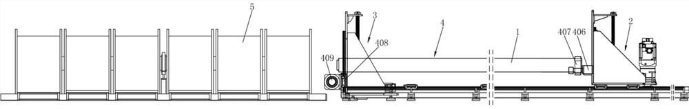
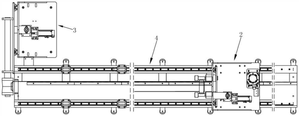
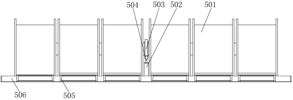
[0033] see Figure 1-2 , the present invention pro...


PUM


Abstract

The present invention relates to the technical field of warp knitting machines, in particular to automatic shaft penetrating and disassembling equipment which structurally includes a warp beam and a first lifting mechanism, wherein the first lifting mechanism is used for lifting one end of the warp beam, lowering a supporting rod to the lowest point and placing the warp beam above the supporting rod and a warp beam limiting frame; a second motor and a third motor respectively drive a first ball screw and a second ball screw to move upwards, the motors stop moving after reaching positions set by a system, a first motor is started to drive a gear to move through an axial pan head center hole under the guiding action of a rack, the motor stops moving after reaching a position designated by the system, the second motor and the third motor are started and lowered to designated positions, and thus, shaft assembly is completed; shaft disassembly is opposite to shaft penetrating, shaft penetrating and disassembling are driven by the motors to operate, so that labor is saved, safety is achieved, and the efficiency is high; the ball screws of worm wheels and worms have a self-locking function during lifting, noise is low, and the service life is long; and a vertical guide rail may bear loads in different directions, so that the stability is good.

Description

technical field [0001] The invention relates to the technical field of warp knitting machines, in particular to an automatic shaft loading and unloading device. Background technique [0002] At present, in the warp knitting machine industry, the process of loading and unloading the pan head is mainly to manually insert or pull out the warp beam into the preset pan head group, which has slow efficiency, many safety hazards, high labor intensity for workers, and poor installation effect. The coordination between the beam and the pan head is completely aligned with the naked eye, making the action of threading the beam extensive and dangerous, and it is easy to cause damage to the warp beam and the pan head. The health of the personnel is extremely vulnerable to greater damage. On the other hand, the conventional method is to directly place the warp beam on the lifting mechanism by the aerial crane, which is easy to smash the lifting mechanism. [0003] The prior art discloses...

Claims


Application Information

Patent Timeline
Patent Type & Authority Applications(China)
IPC IPC(8): B25B27/02B23P19/02
CPCB23P19/02B25B27/02
Inventor 蔡清来田杰吴康强
Owner WORLD LINKING FUJIAN TECH CO LTD
Why Eureka
Eureka Blog
Learn More