Method for producing ink jet printer and ink jet printer

An inkjet printer and ink technology, which is applied in printing, computer parts, permanent visual display devices, etc., can solve the problems of thicker thin lines, broken characters, and worn characters

Active Publication Date: 2021-06-22
SEIKO EPSON CORP
View PDF12 Cites 0 Cited by
  • Summary
  • Abstract
  • Description
  • Claims
  • Application Information

AI Technical Summary

Problems solved by technology

[0003] However, there is a problem that if the amount of ink reduction by edge processing is too large, characters will be frayed or thin lines will be missing, and on the other hand, if the amount of ink reduction is too small , it will cause the text t

Method used


Image

  • Method for producing ink jet printer and ink jet printer
  • Method for producing ink jet printer and ink jet printer
  • Method for producing ink jet printer and ink jet printer

Examples


no. 1 approach

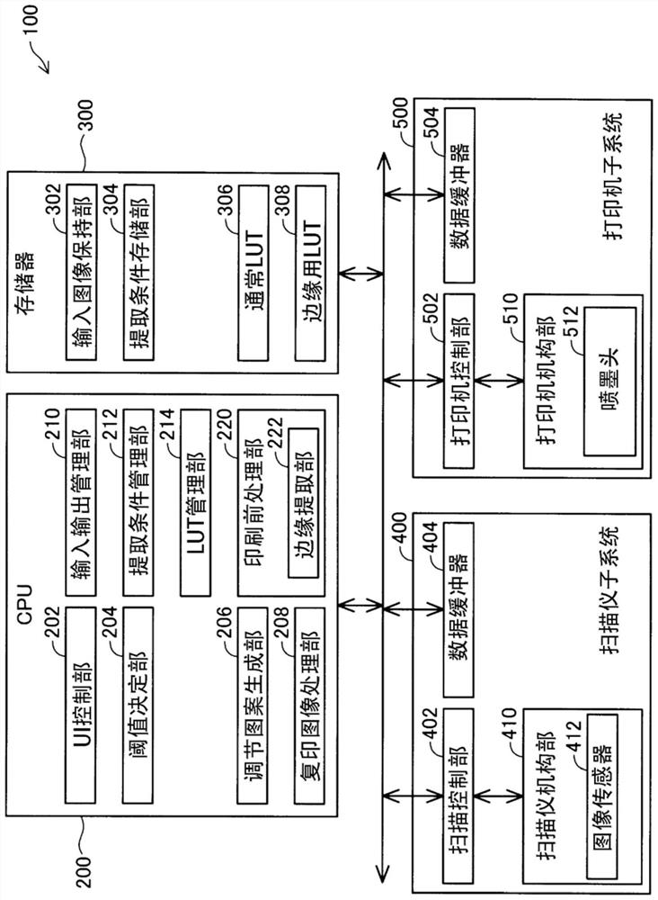
[0019] figure 1 is a block diagram of the inkjet printer 100 of the first embodiment. The inkjet printer 100 includes a CPU (Central Processing Unit: Central Processing Unit) 200 , a memory 300 , a scanner subsystem 400 , and a printer subsystem 500 . The inkjet printer 100 is a multifunction printer having a printer function, a scanner function, and a copy function. The copy function refers to a function of printing an image read using a scanner function. CPU 200 and printer subsystem 500 function as a "printing unit" in the present disclosure.

[0020] The CPU 200 realizes a UI (User Interface: User Interface) control unit 202, a threshold value determination unit 204, an adjustment pattern generation unit 206, a copy image processing unit 208, an input / output management unit 210, an extraction condition management unit 212, a LUT (Look Up Table: lookup table ) functions of the management unit 214 and the pre-printing processing unit 220 . These functions are realized by...

no. 2 approach

[0078] Figure 7 is an explanatory diagram showing an example of the overall adjustment pattern image PTall printed in the second embodiment. The device structure of the second embodiment and figure 1 The device structure of the first embodiment shown is the same, and, Figure 4 Steps S100 to S300 in the processing procedure are also the same as those in the first embodiment. In the second embodiment, when the operator uses Figure 7 As shown in the integrated adjustment pattern image PTall to perform the equivalent of Figure 4 The behavior of steps S400, S500, and S600 is different from that of the first embodiment.

[0079] Figure 7 The integrated adjustment pattern image PTall includes all adjustment pattern images PT_1 to PT_n that are printed by performing edge processing using a plurality of edge extraction threshold candidate values ​​Th_1 to Th_n, respectively. In addition, candidate numbers PN indicating ordinal numbers of a plurality of candidate values ​​Th_...

no. 3 approach

[0082] Figure 8 is a block diagram of the inkjet printer 100a of the third embodiment. The structure of the third embodiment differs from that of the first embodiment in the following points.

[0083] Function of CPU200

[0084] (1) The threshold value determination unit 204 of the first embodiment is replaced with the bottom value determination unit 205 .

[0085] (2) The extraction condition management unit 212 of the first embodiment is omitted, and the LUT management unit 214 is replaced with the gradation conversion table management unit 230 .

[0086] (3) While the pre-printing processing unit 220 of the first embodiment includes the edge extraction unit 222 , the pre-printing processing unit 220 a of the third embodiment includes the line drawing extraction unit 224 and the gradation conversion unit 226 .

[0087] Contents of memory 300

[0088] (1) The extraction condition storage unit 304 and the edge LUT 308 are omitted.

[0089] (2) The normal gradation conver...


PUM


Abstract

The present invention provides a method for producing an ink jet printer, and an ink jet printer, and provides a technique capable of realizing an appropriate pre-printing treatment under conditions in which an average concentration is not reduced due to an excessive pre-printing treatment, or the average concentration is not increased due to an insufficient pre-printing treatment by including a step in which the average concentration is not reduced due to an excessive pre-printing treatment, wherein the step is a step of printing a first image including a plurality of edge pixels and a second image having a smaller proportion of edge pixels than the first image and having an average density equal to that of the first image, and a step of determining a value of a processing parameter so that the average density in the first image and the second image is consistent.

Description

technical field [0001] The present disclosure relates to an inkjet printer. Background technique [0002] In inkjet printing, ink on the darker side bleeds to the thinner side in edge pixels with a large difference in shading between adjacent parts, so that either the image becomes blurred or the bleed The color at the bleed has more influence than the color at the source of the bleed, so the color as a whole also gets darker. Therefore, conventionally, edge processing to suppress ink bleeding by reducing the amount of ink in edge pixels has sometimes been performed as pre-printing processing. In Patent Document 1, one such edge processing is disclosed. [0003] However, there is a problem that if the amount of ink reduction by edge processing is too large, characters will be worn out or thin lines will be missing, and on the other hand, if the amount of ink reduction is too small , there will be cracking of characters or thickening of thin lines caused by ink bleeding. ...

Claims


Application Information

Patent Timeline
IPC IPC(8): B41J2/045
CPCB41J2/04595B41J2/175B41J2/2121G06K15/107G06K15/1847B41J2/2114G06K15/102
Inventor 小山文夫篠原慎平
Owner SEIKO EPSON CORP
Why Eureka
Try Eureka