A composite cross-arm structure

A cross-arm, together technology, applied in the direction of towers, building types, buildings, etc., can solve the problems of composite cross-arm failure, stress concentration, stiffness difference, etc., to achieve the effect of improving bearing capacity, improving bearing capacity, and reducing stiffness changes

Active Publication Date: 2022-05-06
NORTH CHINA ELECTRIC POWER UNIV (BAODING)
View PDF7 Cites 0 Cited by
  • Summary
  • Abstract
  • Description
  • Claims
  • Application Information

AI Technical Summary

Problems solved by technology

[0005] The present invention provides a composite cross-arm structure, which can effectively solve the problem caused by the difference in rigidity between the composite material and the 45 steel material proposed in the above-mentioned background technology. The rigidity of the joint between the mandrel and the flange changes abruptly. After the load is applied, the Stress concentration will occur, which will cause the failure of the composite cross-arm as a whole

Method used


Image

  • A composite cross-arm structure
  • A composite cross-arm structure
  • A composite cross-arm structure

Examples


Embodiment 1

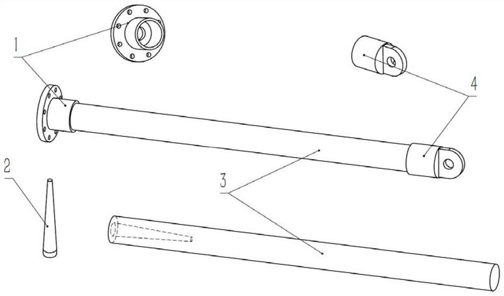
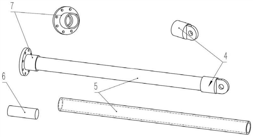
[0026] Such as Figure 1-2 As shown, the present invention provides a technical solution, a composite cross-arm structure, including flanges, inner shafts, mandrels, and end connectors 4. The flanges include A-type flanges 1 and B-type flanges. There are two types of flange 7, the inner shaft has two types of A-type inner shaft 2 and B-type inner shaft 6, and the A-type flange 1 and A-type inner shaft 2 are used for the connection of the extruded mandrel 3, which is convenient for the A-type inner shaft 2 for installation, after the extruded mandrel 3 is extruded, a hole with the same length as the A-type inner shaft 2 and 20mm smaller than the A-type inner shaft 2 is processed at one end, and the B-type flange 7 and B The inner shaft 6 is applied to the connection of the winding mandrel 5, which is convenient for installing the B-type inner shaft 6. When the winding mandrel 5 is wound and formed, the glass fiber is wound on the B-type inner shaft 6 and the mold, so that the B...

Embodiment 2

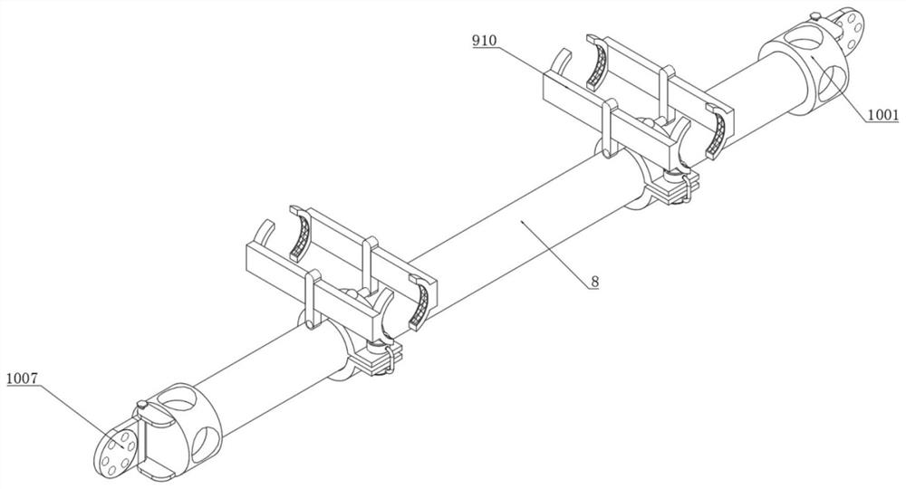
[0036] Such as Figure 3-6 As shown, the present invention provides a technical solution, a composite cross-arm assembly and fixing structure, including a connecting rod 8, and a placing mechanism 9 is symmetrically installed on the outer end of the connecting rod 8, and the placing mechanism 9 includes a clamp 901, a first threaded hole 902 , fastening bolt 903, first bolt seat 904, protective sleeve 905, rubber connecting rod 906, rolling ball 907, fixed rod 908, support plate 909, extension plate 910, limit plate 911, embedded groove 912, rubber pad 913 and Anti-slip mat 914;

[0037]The outer end of the connecting rod 8 is symmetrically slidably sleeved with a clamp 901. A first threaded hole 902 is provided at one side of the top of the clamp 901. The first threaded hole 902 is internally threaded with a fastening bolt 903. The bottom end of the clamp 901 has a The first bolt seat 904 is welded at the side position, which is convenient for fixing the clamp 901. The outer...


PUM


Abstract

The invention discloses a composite cross-arm structure, which consists of four parts: a flange, an inner shaft, a mandrel and an end connector. The flange has two types: A-type flange and B-type flange, and the inner shaft has a There are two types of inner shafts and B-type inner shafts. A-type flanges and A-type inner shafts are used for the connection of extruded mandrels, and B-type flanges and B-type inner shafts are used for the connection of winding-type mandrels. The flange and the inner shaft are connected by threads. The structure of the present invention is equipped with a composite cross-arm structure, and the end displacement is relatively small when subjected to lateral loads. The role of the mandrel can further improve the applicability of the composite cross-arm structure. At the same time, the composite cross-arm structure can transmit force to the fixed end through the two parts of the inner shaft and the flange during actual operation, which can effectively reduce the cross-arm structure. The rigidity change between the arm and the flange increases the load-bearing capacity of the cross-arm, thereby increasing the stiffness of the cross-arm.

Description

technical field [0001] The invention relates to the field of composite cross-arm manufacturing, in particular to a composite cross-arm structure. Background technique [0002] Glass fiber reinforced composite material is made by mixing glass fiber and matrix material in proportion. It has the advantages of light weight, high strength, insulation, corrosion resistance and low cost. It can overcome the defects of traditional materials such as wood, steel and concrete for power construction. In recent years, it has been widely used in transmission line poles and towers. The crossarm is a cantilever structure used to hang transmission lines on transmission line poles and towers. It is made of composite materials, which can reduce the frequency of faults such as lightning breakdown and pollution flashover, and reduce the transmission cost. The height and width of the corridor reduce the height and weight of transmission towers, reduce operation and maintenance costs, and improve ...

Claims


Application Information

Patent Timeline
Patent Type & Authority Patents(China)
IPC IPC(8): E04H12/24
CPCE04H12/24
Inventor 安利强王志旭
Owner NORTH CHINA ELECTRIC POWER UNIV (BAODING)
Why Eureka
Try Eureka