
Monitoring camera for intelligent security and protection system

A surveillance camera, intelligent security technology, applied in CCTV systems, components of TV systems, image communication, etc., can solve the problems of wasting manpower and material resources, trouble, system redundancy, etc., to achieve the effect of wasting manpower and material resources

Active Publication Date: 2021-06-22
山西慧通智能化工程有限公司
View PDF9 Cites 3 Cited by
  • Summary
  • Abstract
  • Description
  • Claims
  • Application Information

AI Technical Summary

Problems solved by technology

[0002]Security camera refers to the camera used in security protection. Its main features are high sensitivity, small distortion, small size, long life, and can be monitored by remote control. Wide range, security cameras are mainly used by government departments in places with confidential documents such as office buildings. It is necessary to install a security camera for monitoring before it can be monitored, resulting in a limited monitoring range of a single camera, and the installation of multiple cameras will lead to difficulties in forensic analysis, system redundancy, and increased costs in the later stage. Need to gradually search for multiple memory devices
Not only troublesome but also a waste of manpower and material resources

Method used


Image

  • Monitoring camera for intelligent security and protection system
  • Monitoring camera for intelligent security and protection system
  • Monitoring camera for intelligent security and protection system

Examples


Embodiment Construction

[0025] In describing the present invention, it should be understood that the terms "center", "longitudinal", "transverse", "length", "width", "thickness", "upper", "lower", "front", " Orientation indicated by rear, left, right, vertical, horizontal, top, bottom, inside, outside, clockwise, counterclockwise, etc. The positional relationship is based on the orientation or positional relationship shown in the drawings, and is only for the convenience of describing the present invention and simplifying the description, rather than indicating or implying that the referred device or element must have a specific orientation, be constructed and operated in a specific orientation, Therefore, it should not be construed as limiting the invention.

[0026] In the description of the present invention, "plurality" means two or more, unless otherwise specifically defined.

[0027] In the description of the present invention, it should be noted that, unless otherwise specified and limited, t...


PUM


Abstract

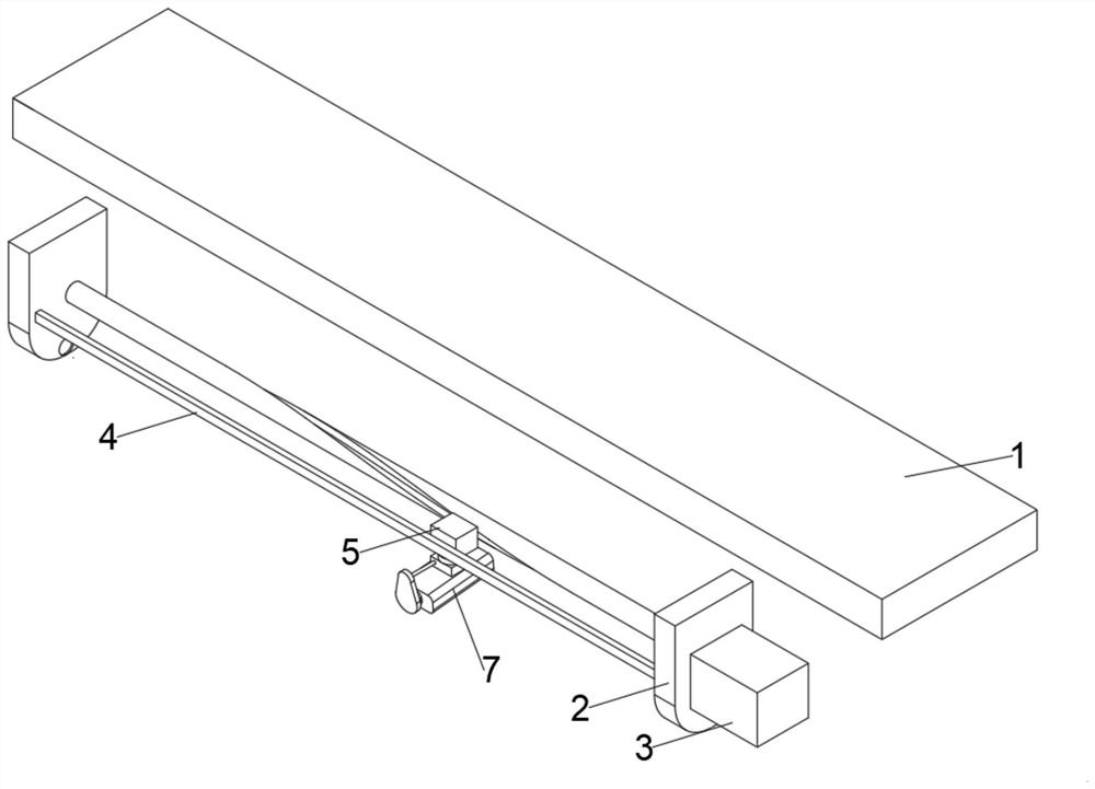
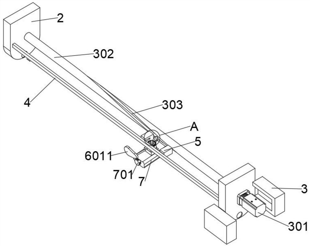
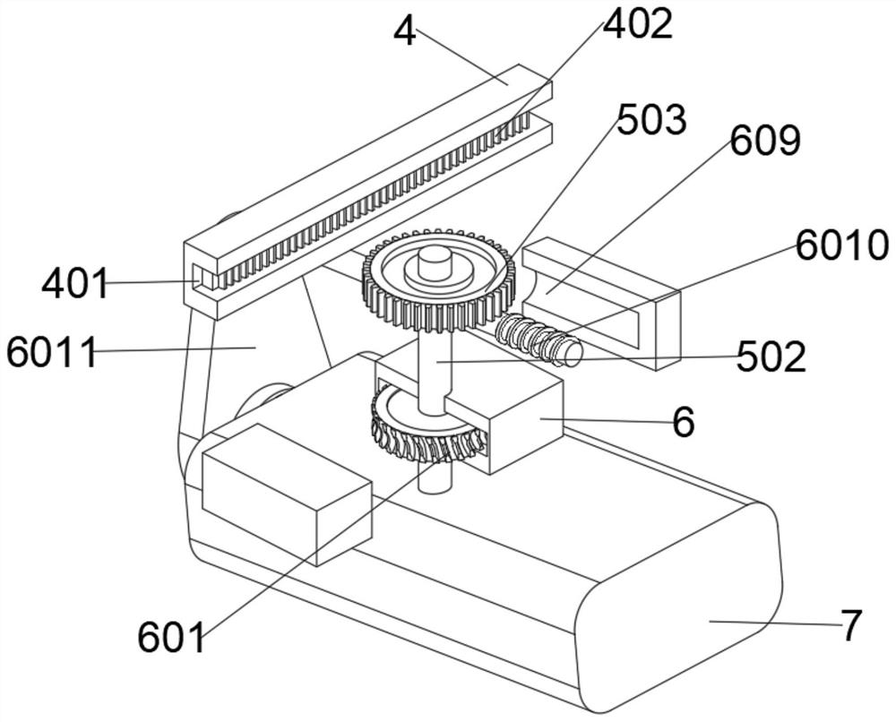
The invention discloses a monitoring camera for an intelligent security and protection system and belongs to the technical field of security and protection. The monitoring camera for the intelligent security and protection system comprises a wall, wherein two fixed lugs are symmetrically and fixedly arranged at the middle part of the bottom surface of the wall, a motor is fixed in a crate through screws, the output end of the motor penetrates through the inner wall of the crate, the outer walls of the fixed lugs extend into the crate and are coaxially connected with a cylinder, a limiting block is arranged on the front side of the cylinder, a limiting groove is formed in the middle part of the outer wall of the rear side of the limiting block, a rack is fixedly arranged on the inner wall of the limiting groove, a rotating shaft is rotationally connected to the middle part of the interior of a cavity, a gear is connected to the outer wall of a circumference of the rotating shaft in a sleeved manner, and a cam is fixedly arranged at the middle part of the outer wall of the rear side of a moving block. Through close fit of the structures, the device can monitor the position in front of an office door and further monitor the interior of an office through a window of the office at the same time, so that the trouble that a plurality of cameras need to be arranged and the situation that the plurality of cameras cannot perform continuous monitoring are avoided.

Description

technical field [0001] The invention relates to the field of security technology, more specifically, to a monitoring camera for an intelligent security system. Background technique [0002] Security camera refers to the camera used in security protection. Its main features are high sensitivity, small distortion, small size, long life, remote control and monitoring, and wide range. Security cameras are mainly used in government departments in office buildings and other places. However, the existing security cameras can only be fixed at the position in front of the office door and only rotate for monitoring, while the corridors, offices and doors and windows need to be monitored by installing security cameras to monitor them, resulting in The monitoring range of a single camera is limited, and the installation of multiple cameras will lead to difficulties in forensic analysis, system redundancy and increased costs in the later stage, and the search for forensic surveillance vi...

Claims


Application Information

Patent Timeline
Patent Type & Authority Applications(China)
IPC IPC(8): F16M11/04F16M11/08F16M11/18F16M13/02H04N5/232H04N7/18B08B1/00B08B1/04
CPCF16M13/02F16M11/045F16M11/18F16M11/08H04N7/185H04N23/695B08B1/143B08B1/32
Inventor 杨友生
Owner 山西慧通智能化工程有限公司
Learn More