Optical system, image capturing module and electronic device
An optical system and module technology, applied in the field of infrared detection, can solve the problems of increasing the difficulty of lens processing and increasing the production cost of infrared thermometers, and achieve the effects of reducing production costs, reducing processing difficulty, and extending the range of depth of field
- Summary
- Abstract
- Description
- Claims
- Application Information
AI Technical Summary
Problems solved by technology
Method used
Image

Examples
Embodiment 1
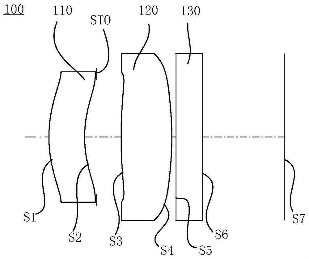
[0083] Please refer to Figure 1 to Figure 2C As shown, the optical system 100 includes a first lens 110 , a stop STO, a second lens 120 , a protective glass 130 and an imaging surface S7 arranged in sequence along the optical axis from the object side to the image side.
[0084] The first lens 110 has positive refractive power, the object side S1 of the first lens 110 is convex at the near optical axis, and the image side S2 of the first lens 110 is concave at the near optical axis. The second lens 120 has positive refractive power. The object side S3 of the second lens 120 is convex at the near optical axis, and the image side S4 of the second lens 120 is also convex at the near optical axis.
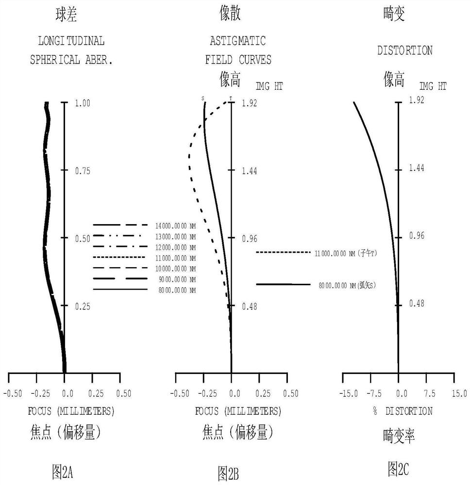
[0085] In the first embodiment, the reference wavelength of the focal length of each lens is 10000.000 nm, and the reference wavelength of the Abbe number and the refractive index are both 587.56 nm. The relevant parameters of the optical system 100 are shown in Table 1, wherein, in ...
Embodiment 2
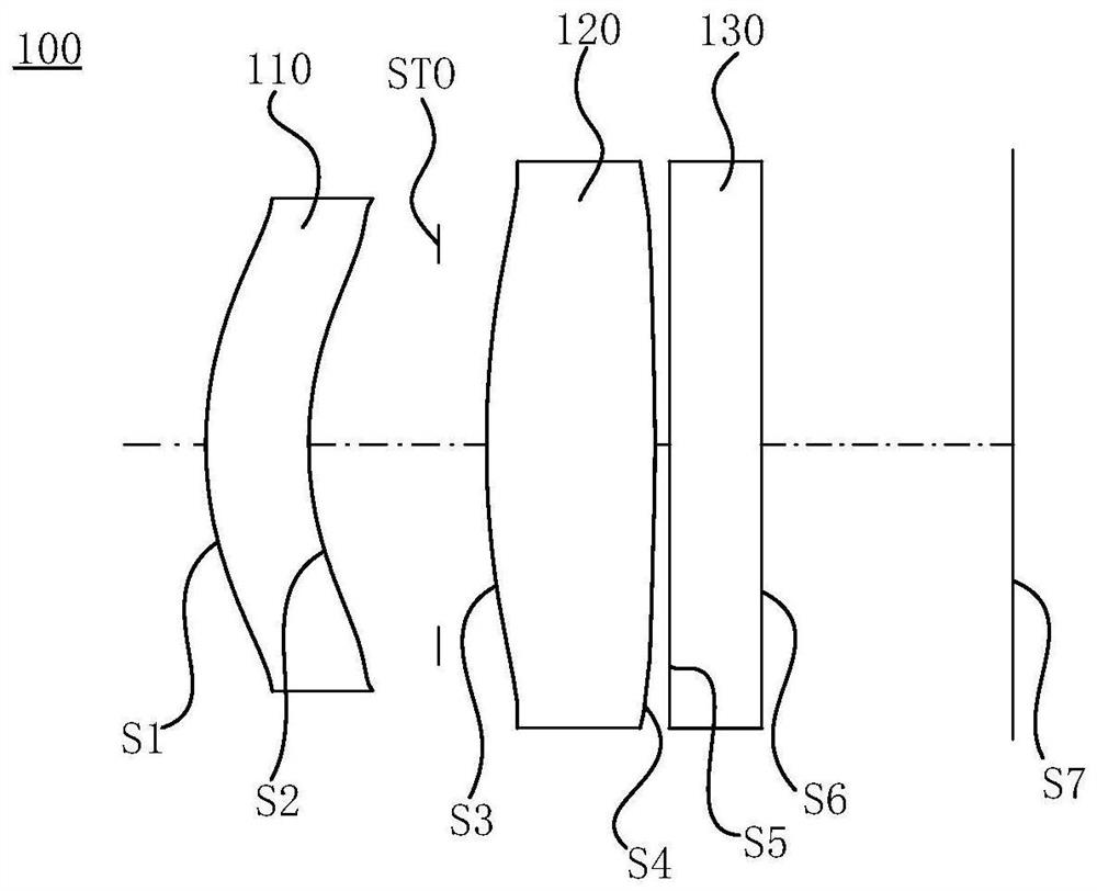
[0099] Please refer to Figure 3 to Figure 4C As shown, the optical system 100 includes a first lens 110 , a stop STO, a second lens 120 , a protective glass 130 and an imaging surface S7 arranged in sequence along the optical axis from the object side to the image side.
[0100] The first lens 110 has positive refractive power, the object side S1 of the first lens 110 is convex at the near optical axis, and the image side S2 of the first lens 110 is concave at the near optical axis. The second lens 120 has positive refractive power. The object side S3 of the second lens 120 is convex at the near optical axis, and the image side S4 of the second lens 120 is also convex at the near optical axis.
[0101] In the second embodiment, the definitions of the relevant parameters of the optical system 100 are the same as those in the first embodiment, and will not be repeated here. The object side S1 of the first lens 110, the image side S2 of the first lens 110, and the object side S3...
Embodiment 3
[0110] Please refer to Figure 5 to Figure 6C As shown, the optical system 100 includes a first lens 110 , a stop STO, a second lens 120 , a protective glass 130 and an imaging surface S7 arranged in sequence along the optical axis from the object side to the image side.
[0111] The first lens 110 has positive refractive power, the object side S1 of the first lens 110 is convex at the near optical axis, and the image side S2 of the first lens 110 is concave at the near optical axis. The second lens 120 has positive refractive power. The object side S3 of the second lens 120 is convex at the near optical axis, and the image side S4 of the second lens 120 is also convex at the near optical axis.
[0112] In the third embodiment, the definitions of the relevant parameters of the optical system 100 are the same as those in the first embodiment, and will not be repeated here. The object side S1 of the first lens 110, the image side S2 of the first lens 110, and the object side S3 ...
PUM
 Abstract
Description
Claims
Application Information
PatSnap Eureka turns technology decisions into work you can execute. Powered by our Innovation Knowledge Graph, it runs expert workflows across engineering, life sciences, materials and intellectual property. Get your review-ready output in minutes.


