
Lane line detection method and system

A lane line detection and lane line technology, applied in the field of image recognition, can solve problems such as lane line occlusion, lane line missed detection, and limited computing power, and achieve the effects of improving accuracy, alleviating lane line missed detection, and enhancing feature expression

Pending Publication Date: 2021-06-22
SOUTH CHINA UNIV OF TECH
View PDF0 Cites 1 Cited by
  • Summary
  • Abstract
  • Description
  • Claims
  • Application Information

AI Technical Summary

Problems solved by technology

[0003] Since most of the intelligent driving systems run on embedded devices, that is to say, the computing power is limited, and the lane line detection is faced with a real-time and complex environment, so the current lane line detection methods still have many defects
For example: (1) The lane line detection method based on semantic segmentation is a two-stage method, and the complex post-processing makes this method run slowly, it is difficult to migrate to embedded devices, and cannot meet the real-time requirements; (2) Line-based The classification method does not use the prior knowledge of long and thin lane lines. Although the speed is fast, it is easy to cause missed detection of lane lines in practical applications; (3) The most common problems in lane line detection include lane line occlusion , abrasion, and the proportion of lane line pixels in the whole picture is too small, etc. Usually, alleviating the occlusion problem needs to be combined with the context. In addition, if the proportion of lane line pixels is too small, feature expression needs to be strengthened, and the existing anchor-based methods do not fully consider these issues

Method used


Image

  • Lane line detection method and system
  • Lane line detection method and system
  • Lane line detection method and system

Examples


Embodiment 1

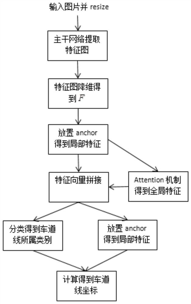
[0037] Such as figure 1 As shown, a lane line detection method is a process of constructing a detection lane line model, including:

[0038] S1 inputs the picture to be detected, the picture to be detected includes the lane, and the acquisition device is a camera, installed in front of the intelligent driving vehicle, and resized to a size of 320*640.

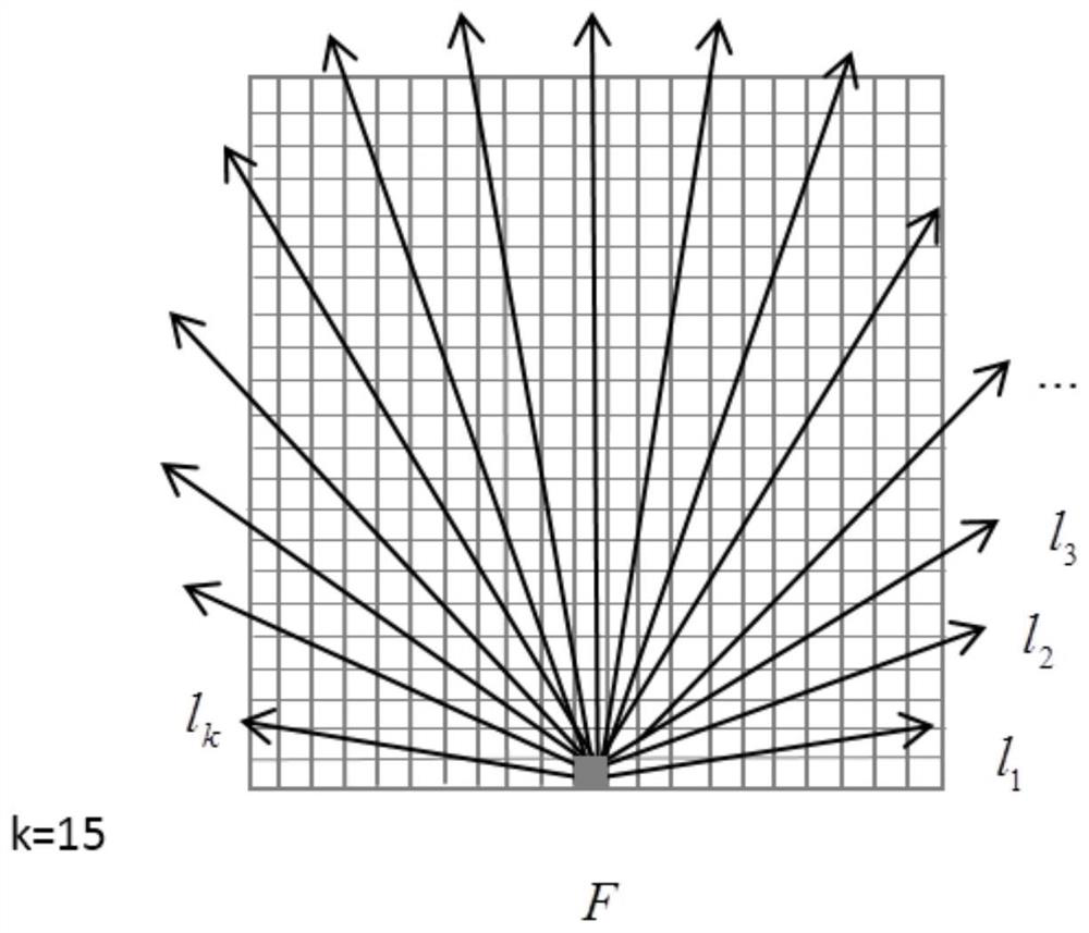
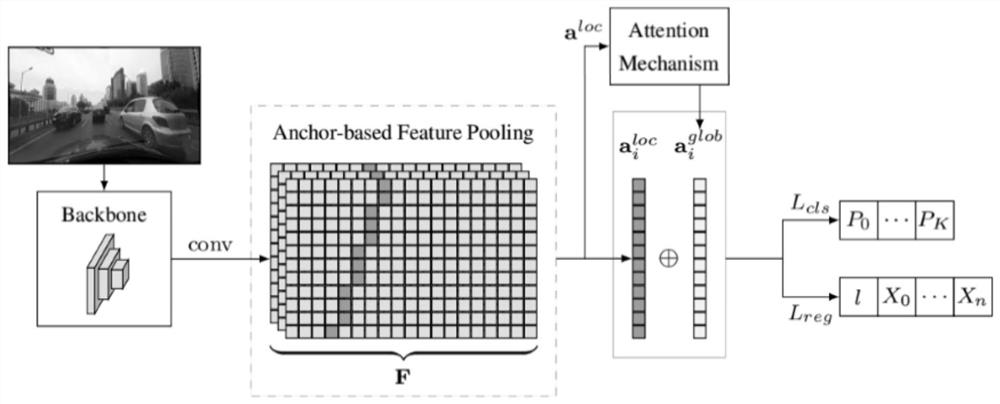
[0039] S2 as image 3 As shown, use the resnet34 network as the backbone network to extract the feature map F, and add a DCT-basedglobal context block to the last layer of c3, c4, and c5 of the backbone network (ie, the 3rd, 4th, and 5th convolutional Block blocks of Resnet34) to Extract the global context features, and strengthen the lane features.

[0040] image 3 Among them, backbone represents the backbone network, conv represents a 1*1 convolutional layer, and L cls and L reg Represents two parallel fully connected networks.

[0041] S3 uses 1*1 convolution layer to feature map F back Dimensionality reduction to ob...

Embodiment 2

[0051] A lane line detection system, comprising:

[0052] Acquisition module, used for obtaining the image to be detected;

[0053] The feature map acquisition module is used to obtain the feature map of the image to be detected by the resnet34 network equipped with the DCT-based Global Context Block, as shown in Figure 4(a) and Figure 4(b) for the structure of the DCT-based Global Context Block schematic diagram.

[0054] The feature map dimensionality reduction module uses a 1*1 convolutional layer to reduce the dimensionality of the feature map of the feature map acquisition module,

[0055] Prediction module: specifically two parallel fully connected networks, one for classification and one for regression.

[0056] The above five parts constitute the entire detection model.

[0057] Model training process:

[0058] Kmeans pre-acquires the angle of the anchor——input picture——after the detection model outputs the predicted category, offset value and length—calculates the...


PUM


Abstract

The invention discloses a lane line detection method and system. The method comprises the steps: collecting a to-be-detected picture, obtaining a feature map of the to-be-detected picture, obtaining a local feature vector and a global feature vector according to the feature map, splicing the local feature vector and the global feature vector, inputting the two vectors into two parallel full-connection networks, and predicting the type, deviation value and length of a lane. According to the invention, the contextual information of the lane line is utilized, and the accuracy of lane line detection is improved under the condition that the speed is not obviously reduced.

Description

technical field [0001] The invention relates to the field of image recognition, in particular to a lane line detection method and system. Background technique [0002] Lane line detection is a key part of intelligent driving technology. The detected lane line information can be used for driving route planning, road departure reminder and traffic accident avoidance. There are many lane line detection methods, which can be divided into two categories: one is the detection method based on traditional digital image processing, and the other is the lane line detection method based on neural network and deep learning technology. Although detection methods based on traditional digital image processing such as Hough transform are simple and fast, they are not robust enough to deal with complex background environments (such as occlusion, lane line wear, strong and weak light, etc.); The development of deep learning technology has gradually been applied to the field of lane line dete...

Claims


Application Information

Patent Timeline
IPC IPC(8): G06K9/00G06K9/62G06N3/04G06N3/08
CPCG06N3/084G06V20/588G06N3/047G06N3/045G06F18/23213G06F18/213G06F18/2415G06F18/253G06F18/214Y02T10/40
Inventor 杨漫瑶张艳青程锐
Owner SOUTH CHINA UNIV OF TECH
Learn More