
Looped network type combined transformer

A combined transformer and transformer technology, which is applied in the field of transformer equipment, can solve problems such as inability to directly jump switch, short switching time, and affecting the power supply system, and achieve the effect of free and convenient switching process and guaranteed stability

Active Publication Date: 2021-06-22
中电电气(江苏)变压器制造有限公司
View PDF3 Cites 0 Cited by
  • Summary
  • Abstract
  • Description
  • Claims
  • Application Information

AI Technical Summary

Problems solved by technology

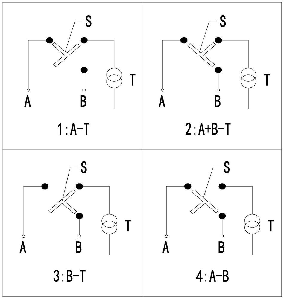
[0007] The conventional ring network combined transformer can easily realize the conversion of the four wiring functions through the conversion of the four-position load switch S, but there is a biggest problem in this conversion method: the four-position load switch S is converted from one wiring When the connection method is switched to another connection method, there must be a short switching time between the two connection methods. power status, affecting the entire power supply system
[0008] In addition, these four wiring functions must be switched clockwise or counterclockwise, and cannot be switched directly
For example, if you want to switch from wiring scheme 1 to wiring scheme 3, you must first switch to wiring scheme 2 or to wiring scheme 4. In this way, two short power failures will occur during the transfer from wiring scheme 1 to wiring scheme 3. When switching from wiring scheme 2 to wiring scheme 4, it will also cause two brief power outages, seriously affecting the entire power supply system

Method used


Image

  • Looped network type combined transformer
  • Looped network type combined transformer
  • Looped network type combined transformer

Examples


Embodiment Construction

[0019] specific implementation plan

[0020] In order to deepen the understanding of the present invention, the present invention will be described in further detail below in conjunction with the examples and accompanying drawings. The examples are only used to explain the present invention and do not constitute a limitation to the protection scope of the present invention.

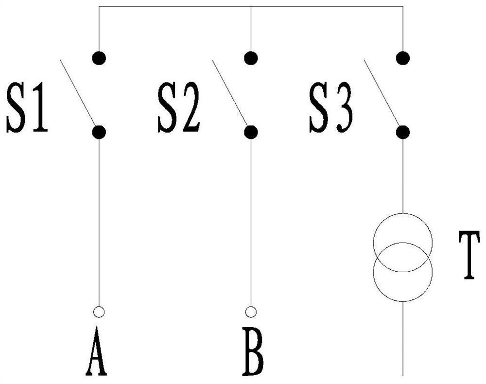
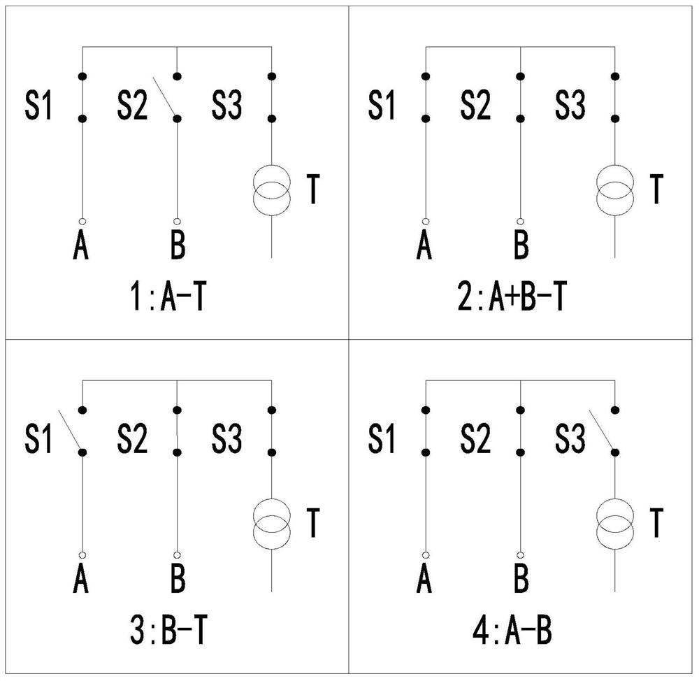
[0021] Such as Figure 2 ~ Figure 3 As shown, A represents power circuit 1, B represents power circuit 2, and T represents transformer circuit: a ring network type combined transformer, including power circuit 1, power circuit 2 and transformer circuit, the power circuit 1, power circuit 2 is connected to the transformer circuit in sequence, the power circuit 1 is provided with a first load switch S1, the power circuit 2 is provided with a second load switch S2, and the transformer circuit is provided with a third load switch S3.

[0022] In this embodiment, the power circuit 1 or the power circuit 2 can...


PUM


Abstract

The invention discloses a looped network type combined transformer which comprises a power supply loop 1, a power supply loop 2 and a transformer loop, the power supply loop 1, the power supply loop 2 and the transformer loop are connected in sequence, the power supply loop 1 is provided with a first load switch S1, the power supply loop 2 is provided with a second load switch S2, and the transformer loop is provided with a third load switch S3. According to the looped network type combined transformer, the three two-station load switches are adopted to replace a four-station load switch in a conventional looped network type combined transformer, various wiring functions can be achieved through free combination of the three two-station load switches, and the switching process of the whole circuit is free and convenient; and the stability of the power supply system can be ensured, and the power failure phenomenon of the transformer or the looped network power supply system is avoided.

Description

technical field [0001] The invention belongs to the technical field of transformer equipment, and in particular relates to a ring network type combined transformer. Background technique [0002] Such as figure 1 As shown, the high-voltage main circuit of the conventional ring network combined transformer uses a four-position load switch S to realize four wiring schemes, where A represents power circuit 1, B represents power circuit 2, and T represents the transformer: [0003] 1) A-T: Power loop 1 supplies power to the transformer alone, and power loop 2 is open; [0004] 2) A+B-T: Power loop 1 and power loop 2 supply power to the transformer together, or power loop 1 supplies power to the transformer while forming a ring network power supply system with power loop 2 (or power loop 2 supplies power to the transformer and power loop 1 at the same time form a ring network power supply system); [0005] 3) B-T: Power loop 2 supplies power to the transformer alone, and power ...

Claims


Application Information

Patent Timeline
Patent Type & Authority Applications(China)
IPC IPC(8): H01F27/40
CPCH01F27/40
Inventor 傅高金
Owner 中电电气(江苏)变压器制造有限公司
Learn More