Movable layer file compact shelf facilitating taking and placing
A technology of compact shelves and active layers, applied in the field of compact shelves, can solve the problems of large storage volume, low security, and inability to store a large number of files, and achieve the effect of convenient separation and time saving.
- Summary
- Abstract
- Description
- Claims
- Application Information
AI Technical Summary
Problems solved by technology
Method used
Image

Examples
Embodiment 1
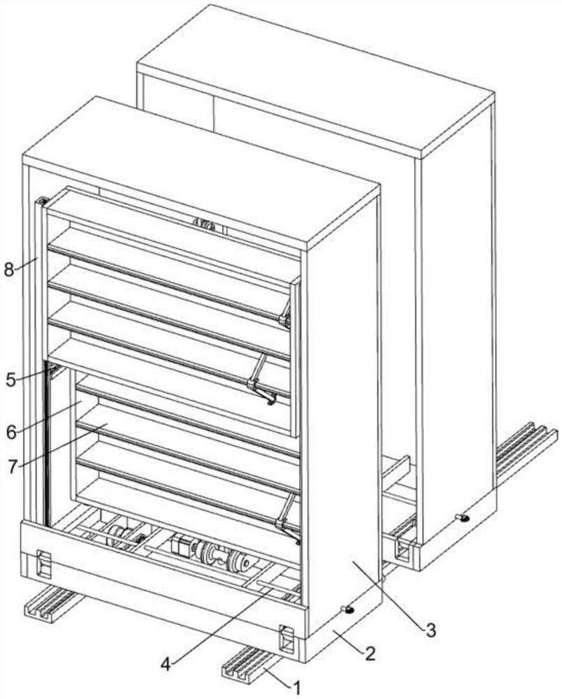
[0028] Such as figure 1 As shown, a movable layer file compact shelf that is easy to pick and place includes a guide rail 1, an underframe 2, a cabinet body 3, a moving mechanism 4, a sliding mechanism 5, a shelf 6, a laminate 7 and a lifting mechanism 8. An underframe 2 is arranged between the two guide rails 1, a cabinet body 3 is arranged on the underframe 2, a moving mechanism 4 is arranged on the underframe 2, a sliding mechanism 5 is arranged inside the cabinet body 3, the The sliding mechanism 5 is provided with a storage rack 6, and the storage rack 6 is provided with three laminates 7, and the cabinet body 3 is provided with a lifting mechanism 8, and the lifting mechanism 8 is provided with a storage rack 6, and in the storage rack 6 Laminates 7 are evenly spaced.
[0029] When the files need to be stored, the moving mechanism 4 drives the cabinet body 3 to move, thereby leaving a gap between the multiple cabinet bodies 3 to facilitate the staff to enter. When movin...
Embodiment 2
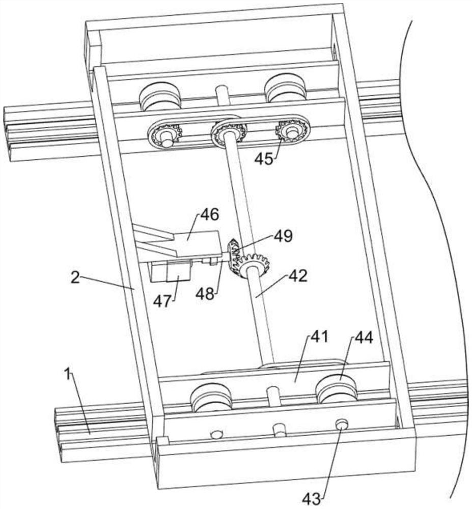
[0031] Such as figure 2 , image 3 with Figure 4As shown, on the basis of Embodiment 1, the moving mechanism 4 includes a rib plate 41, a first rotating shaft 42, a fixed shaft 43, a load wheel 44, a sprocket assembly 45, a fixed seat 46, a first servo motor 47, a second Two rotating shafts 48 and a bevel gear set 49, the left and right sides of the underframe 2 are symmetrically provided with ribs 41, the first rotating shaft 42 is rotatably arranged between the four ribs 41, and the two ribs 41 Both front and rear sides are rotatably provided with fixed shafts 43, and the four fixed shafts 43 are symmetrically provided with bearing wheels 44, and the four on the same side are slidably matched with the guide rail 1 on the same side. A sprocket assembly 45 is arranged between the opposite end of the shaft 43 and the left and right sides of the first rotating shaft 42. The sprocket assembly 45 is composed of four sprockets and two chains. Sprocket, two sprockets are arrang...
Embodiment 3
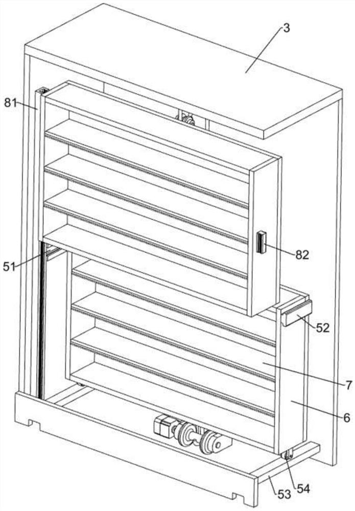
[0038] Such as Figure 5 , Image 6 with Figure 7 As shown, it also includes a U-shaped slider 9, a connecting rod 10 and a triangular slider 11. The front sides of the upper and lower laminates 7 in the two storage racks 6 are all slidably provided with a U-shaped slider 9, The upper and lower sides of the four U-shaped sliders 9 are provided with connecting rods 10, and the rear ends of the eight connecting rods 10 are provided with triangular sliders 11, and the eight triangular sliders 11 are slidably matched with the shelf 6.
[0039] During the movement of the upper and lower storage racks 6, it is easy to cause the files to be dumped and dropped. After the file storage is completed, the staff pushes the U-shaped slider 9 to slide on the laminate 7, and the U-shaped slider 9 slides through the joint. Bar 10 drives triangular slider 11 to slide on rack 6, and U-shaped slider 9 slides to drive connecting rod 10 to move and clamp files. The device has a simple structure...
PUM
 Abstract
Description
Claims
Application Information
 - Generate Ideas
- Intellectual Property
- Life Sciences
- Materials
- Tech Scout
- Unparalleled Data Quality
- Higher Quality Content
- 60% Fewer Hallucinations
Browse by: Latest US Patents, China's latest patents, Technical Efficacy Thesaurus, Application Domain, Technology Topic, Popular Technical Reports.
© 2025 PatSnap. All rights reserved.Legal|Privacy policy|Modern Slavery Act Transparency Statement|Sitemap|About US| Contact US: help@patsnap.com