
Sleeve coiling device

The technology of a sleeve and an outer cylinder is applied in the field of the sleeve winding device, which can solve the problems of lack of friction force for the strip material, the curved surface is not large enough, the strip material is not easy to bend, etc., and achieves a large winding thickness and a large friction force. , Improve the effect of rolling friction

Active Publication Date: 2021-06-25
SHANGHAI WUXING COPPER CO LTD +1
View PDF12 Cites 0 Cited by
  • Summary
  • Abstract
  • Description
  • Claims
  • Application Information

AI Technical Summary

Problems solved by technology

For thicker or more rigid strips, it is difficult to roll them up either by hand or by a belt coiler. The biggest reason is that the strips are not easy to bend and the bending surface in contact with the sleeve is not large enough. , the strip does not get enough friction, causing slippage

Method used


Image

  • Sleeve coiling device
  • Sleeve coiling device
  • Sleeve coiling device

Examples


Embodiment 1

[0027] A sleeve rolling device is used for manual rolling.

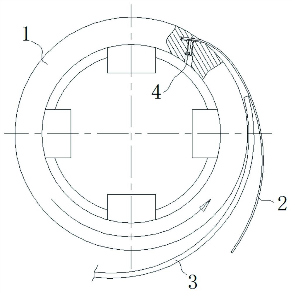
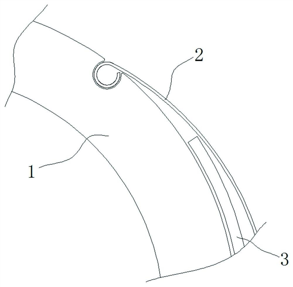
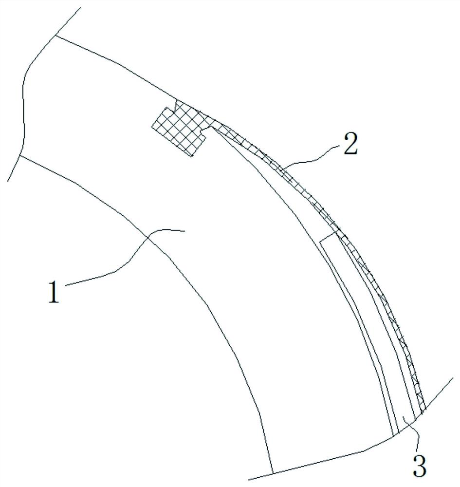
[0028] Such as figure 1 As shown, the sleeve 1 is installed on the main shaft of the coiler, and the main shaft tightens the inner surface of the sleeve 1 through the inner support mechanism, so that the sleeve 1 rotates with the main shaft. The material of the sleeve 1 is metal, which has good rigidity, and is used to support the winding of the metal strip on it. In this embodiment, the metal strip to be wound is a steel strip. Entrainment strip 2 is wound on the outer surface of sleeve 1. In order to prevent the entrainment strip 2 from causing crush to the metal strip, the material of entrainment strip 2 is soft copper or rubber, and its thickness is 1 / 4 of the thickness of the metal strip. one. The head end of the entrainment strip 2 is connected to the sleeve 1, and the rest of the entrainment strip 2 is used to enclose the head 3 of the metal strip, so that the metal strip is wound on the sleeve 1.

[0029] ...

Embodiment 2

[0036] A sleeve rolling device, the difference from Embodiment 1 is that this rolling device is used to assist rolling.

[0037] Such as Figure 5As shown, in addition to the structure described in Embodiment 1, the winding device also includes a pressure roller 5 and a pair of pinch rollers 7 . A pair of pinch rollers 7 are arranged on the lower right side of the sleeve 1, one of which is fixed, and the other pinch roller 7 is driven by the cylinder 6 to clamp the belt 2. When the sleeve 1 rotates, the pair of pinch rollers The tight roller 7 tensions the entrainment belt 2, and plays the role of manually tightening the entrainment belt 2 downwards in the embodiment 1. Compared with the embodiment 1, the labor intensity of this method is lower and safer.

[0038] A pressing roller 5 is arranged on the right side of the sleeve 1, and the pressing roller 5 is driven by another air cylinder 6. As the diameter of the roll changes, the air cylinder 6 can elastically press the ent...


PUM


Abstract

The invention discloses a sleeve coiling device used for coiling a metal strip on a sleeve. A wrapping and clamping belt is wound on the sleeve, the head end of the wrapping and clamping belt is connected with the sleeve, and the rest part of the wrapping and clamping belt is used for wrapping and clamping the strip head of the metal strip, so that the strip head of the metal strip is bent and deformed. After being bent and deformed, the strip head is attached to the sleeve and the wrapping and clamping belt and generates friction force to drive the metal strip to be coiled. According to the sleeve coiling device, the friction force generated on the metal strip is large, the metal strip is not easy to slip, and the coiling thickness is large, so that the sleeve coiling device is especially suitable for coiling thicker or higher-rigidity strips, and the pain point in the industry is solved. The sleeve coiling device has the unexpected beneficial effect that the problem of a strip head impression is solved. Due to the fact that the strip head is wrapped in the wrapping and clamping belt when the wrapping and clamping belt wraps, clamps and coils the metal strip, the strip body is prevented from being crushed by the strip head, the problems which are difficult to solve in the industry are solved, and great loss to the production of the strip caused by cutting off impressions at two ends of the metal strip is avoided.

Description

technical field [0001] The invention relates to the technical field of metal strip rolling, in particular to a sleeve coiling device. Background technique [0002] In the production process of steel and non-ferrous metal strips, especially during rolling, degreasing and finishing, the metal strips must be uncoiled and coiled many times. Before coiling, the head of the metal strip needs to be wound on the sleeve, and then the sleeve is rotated, relying on the friction of the sleeve to the strip to drive the strip to rotate with the sleeve. This process is called coiling. Rolling up can be realized manually or by a belt winding aid. For thicker or more rigid strips, it is difficult to roll them up either by hand or by a belt coiler. The biggest reason is that the strips are not easy to bend and the bending surface in contact with the sleeve is not large enough. , the strip does not get enough friction, causing slippage. This is the current pain point in the industry, which ...

Claims


Application Information

Patent Timeline
IPC IPC(8): B21C47/06B21C47/28
CPCB21C47/06B21C47/28
Inventor 项克祥赵敏良陈熊马力徐继玲姜乔夫赵国天
Owner SHANGHAI WUXING COPPER CO LTD
Learn More