
Profile forming production line

A production line and profile technology, applied in the direction of clamping, supporting, positioning devices, etc., can solve the problems of low production efficiency and low replacement efficiency of the production line, and achieve the effect of improving replacement efficiency

Active Publication Date: 2021-06-25
XINXIANG TIANFENG MACHINERY MFG
View PDF9 Cites 1 Cited by
  • Summary
  • Abstract
  • Description
  • Claims
  • Application Information

AI Technical Summary

Problems solved by technology

There are many forming knife modules in the tool magazine. The traditional replacement method is usually to manually find the correct forming knife module and move it to the position required by the forming knife scissors rack for replacement. The replacement efficiency is still low, resulting in low production efficiency of the production line The problem

Method used


Image

  • Profile forming production line
  • Profile forming production line
  • Profile forming production line

Examples


specific Embodiment 1

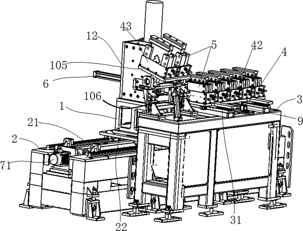
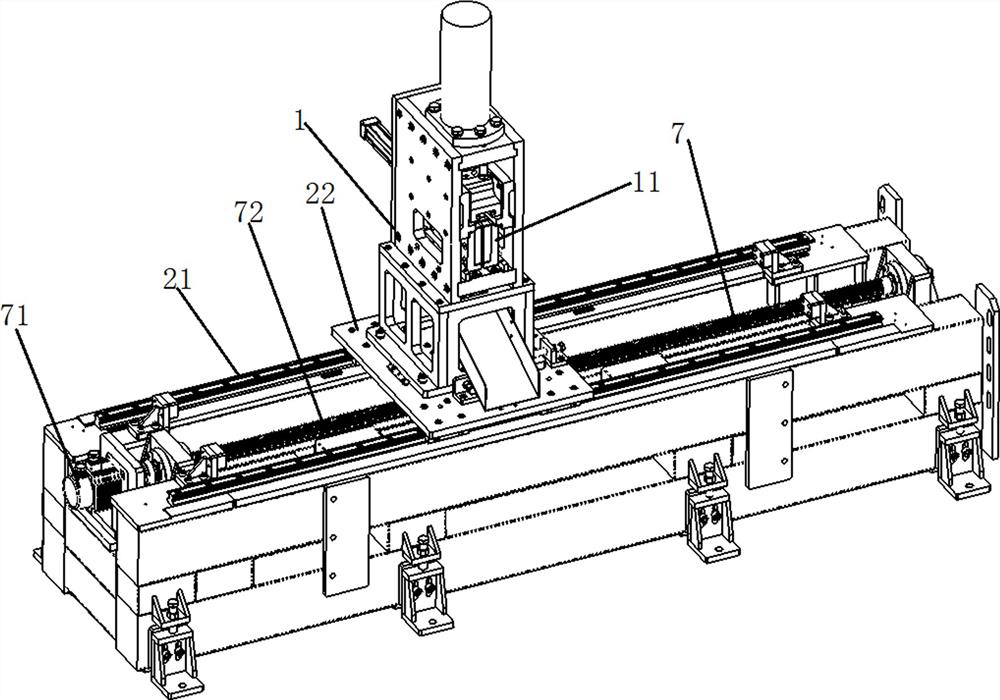
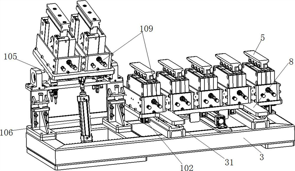
[0039] The profile forming production line includes a profile cold-bending forming device, a shaping device and a forming scissors tool changing device, an automatic tool changing device and a shaping device for formed parts, and a profile cold-bending forming device are arranged in the direction of movement of the profile, from back to front during the profile forming process linear motion. Such as Figure 1 to Figure 8 As shown, the forming scissors tool changing device includes a forming knife and scissors frame 1, a knife and scissors frame moving platform 2, a knife magazine platform 3 and a knife magazine 4 arranged on the knife magazine platform 3. The forming scissors tool changing device in this embodiment can realize automatic tool changing, and the forming scissors frame does not need to leave the production line.

[0040]The forming knife scissor frame 1 has a forming knife module chamber for fixing the forming knife module 5, and the forming knife module chamber ...

specific Embodiment 2

[0066] Specific embodiment 2 of the profile forming production line of the present invention, the difference between the structure of the forming scissors tool changing device in this embodiment and the above embodiment is only that: in this embodiment, the tool magazines in the forming scissors tool changing device are all direct-acting Tool magazine. In other embodiments, all tool magazines may also be reversible tool magazines. In other embodiments, each tool magazine may use an independent driving mechanism, or part of the tool magazines may use an independent driving mechanism, and part of the tool magazine may use a shared driving mechanism.

[0067]In the forming scissors tool changing device of the present invention, the driving mechanism of the knife and scissor frame and the driving mechanism of the tool magazine respectively adopt a screw nut mechanism and a driving cylinder. The driving cylinder can be an air cylinder or an oil cylinder. In other embodiments, the d...

specific Embodiment 3

[0068] Specific embodiment 3 of the profile forming production line of the present invention, the difference between the structure of the forming scissors tool changing device in this embodiment and the above-mentioned embodiment is only that: in this embodiment, the forming scissors tool changing device is semi-automatic, and the free tool magazine and The location of the target tool magazine is entered manually. Of course, the knife and scissors drive mechanism can also be manually driven.


PUM


Abstract

The invention relates to a profile forming production line. The profile forming production line comprises a profile cold bending forming device, a shaping device and a forming shear tool changing device. In the profile forming process, the devices move from back to front, the forming shear tool changing device comprises a forming tool shear frame and a forming tool module driving mechanism, and the forming tool shear frame reciprocates forwards and backwards and is arranged on a tool shear frame moving platform. Tool magazines on a tool magazine platform are arranged in the moving direction of the forming tool shear frame. A tool magazine driving mechanism is used for driving the tool magazines to move so that tool magazine openings can be close to and opposite to forming tool module openings. According to the profile forming production line, the tool magazines are movably arranged on the tool magazine platform of the forming shear tool changing device, all the tool magazines are arranged in the moving direction of the forming tool shear frame, after the forming tool shear frame moves to the target tool magazine, the tool magazine driving mechanism can drive the corresponding tool magazine to move so that the corresponding tool magazine opening can be close to and opposite to the corresponding forming tool module opening, and then replacement of forming tool modules can be accomplished, and the replacement efficiency of the forming shear forming tool modules is improved.

Description

technical field [0001] The invention relates to a profile forming production line. Background technique [0002] During the profile forming process, it needs to go through multiple processes such as cold bending and shaping. After the forming is completed, it is cut by forming scissors. The traditional forming scissors need to stop the production line during the tool change and undercut grinding process, and the forming scissors are removed by professional personnel. , and then install other forming shears, the efficiency is low in the replacement process. [0003] The Chinese patent application publication number CN112548206A discloses a forming shear capable of quick tool change. The forming knife module in the forming shear is driven by a power cylinder, which can realize quick disassembly, replacement and positioning of the forming knife module. During the replacement, the telescopic drive device greatly improves the replacement efficiency of the forming scissors and re...

Claims


Application Information

Patent Timeline
IPC IPC(8): B23Q3/155B23D31/00
CPCB23D31/00B23Q3/15526B23Q3/1554
Inventor 陈智博杨雪莲司永恒李刚姚瑶李娟李志伟
Owner XINXIANG TIANFENG MACHINERY MFG
Learn More