Automatic propelling device for printing machine template and propelling method of automatic propelling device

A technology for automatic propulsion and printing machines, which is applied to printing machines, general parts of printing machinery, printing, etc. It can solve the problems of increasing the difficulty of template installation, increasing the cost of automatic propulsion devices, and increasing fixed procedures, etc., to reduce equipment components, The effect of saving resources and increasing performance

Inactive Publication Date: 2021-06-25
刘志平
View PDF0 Cites 1 Cited by
  • Summary
  • Abstract
  • Description
  • Claims
  • Application Information

AI Technical Summary

Problems solved by technology

[0002] During the use of the printing machine, a template needs to be used. In order to facilitate the installation of the template, an automatic propulsion device is generally used to insert the template into the printing machine. However, when the template is inserted into the printing machine, a certain angle is required when the template is installed. Therefore, the pallet on which the automatic propulsion device is placed to place the template is inclined to ensure that the template can be directly inserted into the printing machine. When placing the template on the inclined pallet, it is necessary to install a clamp on the pallet to fix the template. It will increase the fixing procedure, increase the difficulty of template installation, and need to install fixtures, which will increase the cost of the automatic propulsion device. Therefore, we propose an automatic template propulsion device and its propulsion method for printing presses

Method used


Image

  • Automatic propelling device for printing machine template and propelling method of automatic propelling device
  • Automatic propelling device for printing machine template and propelling method of automatic propelling device
  • Automatic propelling device for printing machine template and propelling method of automatic propelling device

Examples


Embodiment Construction

[0024] The following will clearly and completely describe the technical solutions in the embodiments of the present invention with reference to the accompanying drawings in the embodiments of the present invention. Obviously, the described embodiments are only some, not all, embodiments of the present invention. Based on the embodiments of the present invention, all other embodiments obtained by persons of ordinary skill in the art without making creative efforts belong to the protection scope of the present invention.

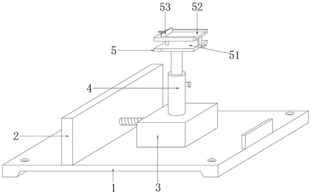
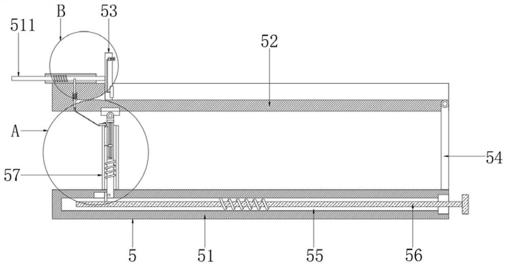
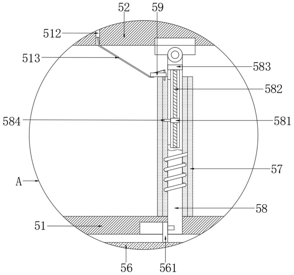
[0025] The present invention provides a technical solution: a printing machine template automatic propulsion device, please refer to figure 1 , including base plate 1 and mounting plate 2;

[0026] see figure 1 , the mounting plate 2 is fixedly installed on the top outer wall of the base plate 1, the mounting seat 3 is slidably installed on the top outer wall of the base plate 1, the motor is installed on the left outer wall of the top of the base plate 1, an...


PUM


Abstract

The invention discloses an automatic propelling device for a printing machine template in the technical field of printing machines. The automatic propelling device comprises a bottom plate and a mounting plate. The mounting plate is fixedly mounted on the outer wall of the top of the bottom plate, a mounting seat is mounted on the outer wall of the top of the bottom plate in a sliding manner, a motor is mounted on the outer wall of the left side of the top of the bottom plate, a right output shaft of the motor is fixedly connected with a threaded sleeve, the right side of an inner cavity of the threaded sleeve is in threaded connection with a threaded rod, the right end of the threaded rod penetrates through the mounting plate and is rotationally connected with the outer wall of the left side of the mounting seat, a telescopic rod is fixedly mounted on the outer wall of the top of the mounting seat, and a supporting device is arranged at the top end of the telescopic rod. According to the automatic propelling device for the printing machine template, a supporting plate is used for supporting the installed template, the template can be horizontally placed in the installation process and does not need to be obliquely arranged in advance, the situation that a clamp needs to be used due to oblique arrangement is avoided, the template installation difficulty is lowered, equipment parts are reduced, and resources are saved.

Description

technical field [0001] The invention relates to the technical field of printing machines, in particular to a printing machine template automatic propulsion device and a propulsion method thereof. Background technique [0002] During the use of the printing machine, a template needs to be used. In order to facilitate the installation of the template, an automatic propulsion device is generally used to insert the template into the printing machine. However, when the template is inserted into the printing machine, a certain angle is required when the template is installed. Therefore, the pallet on which the automatic propulsion device is placed to place the template is inclined to ensure that the template can be directly inserted into the printing machine. When placing the template on the inclined pallet, it is necessary to install a clamp on the pallet to fix the template. It will increase the fixing procedure, increase the difficulty of template installation, and need to inst...

Claims


Application Information

Patent Timeline
Patent Type & Authority Applications(China)
IPC IPC(8): B41F27/04
CPCB41F27/04
Inventor 刘志平
Owner 刘志平
Why Eureka
Try Eureka