
Anti-skid method of milling machine and milling machine

A milling machine and anti-slip technology, which is applied in the field of milling machine control, can solve the problems of increasing the allowable difference between the instant speed of the track wheel and the reference value, the inability to accurately judge the anti-skid phenomenon, and the instability of the adjustment process, and achieve improvement. Slip phenomenon, enhance the anti-skid effect, avoid the effect of slip phenomenon

Active Publication Date: 2021-06-25
SHANTUI CONSTR MASCH CO LTD
View PDF7 Cites 1 Cited by
  • Summary
  • Abstract
  • Description
  • Claims
  • Application Information

AI Technical Summary

Problems solved by technology

[0004] However, in the existing method for judging the slipping phenomenon, in the case of track wheel slippage, the speed of one track wheel increases, and at the same time, the average speed of the four track wheels also changes. During the controller adjustment process, the average speed The value is also constantly changing, which leads to constant changes in the reference value, making it impossible to accurately judge the anti-skid phenomenon, and the adjustment process becomes unstable. In order to avoid this situation, the judgment conditions are often relaxed, that is, the track wheel is enlarged The allowable difference between the instant speed and the reference value leads to the fact that the controller will only adjust when severe slip occurs, and the anti-skid effect is greatly reduced

Method used


Image

  • Anti-skid method of milling machine and milling machine
  • Anti-skid method of milling machine and milling machine
  • Anti-skid method of milling machine and milling machine

Examples


Embodiment Construction

[0042] The present invention will be further described in detail below in conjunction with the accompanying drawings and embodiments. It should be understood that the specific embodiments described here are only used to explain the present invention, but not to limit the present invention. In addition, it should be noted that, for the convenience of description, only some structures related to the present invention are shown in the drawings but not all structures.

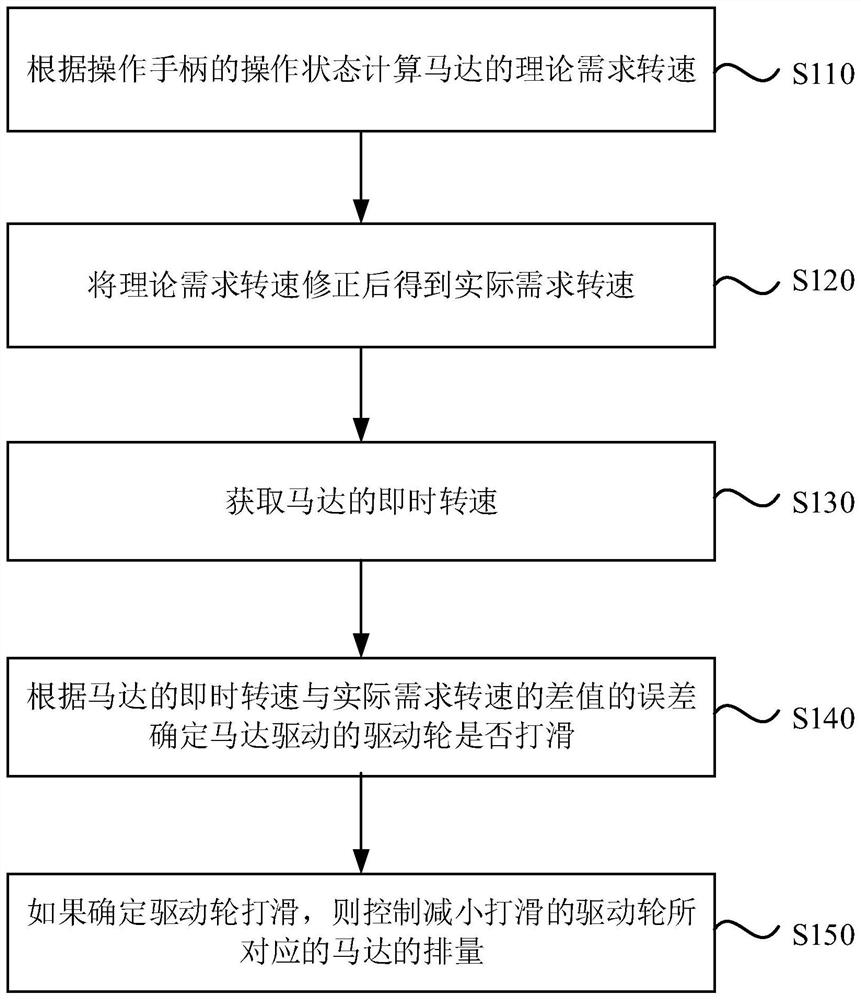
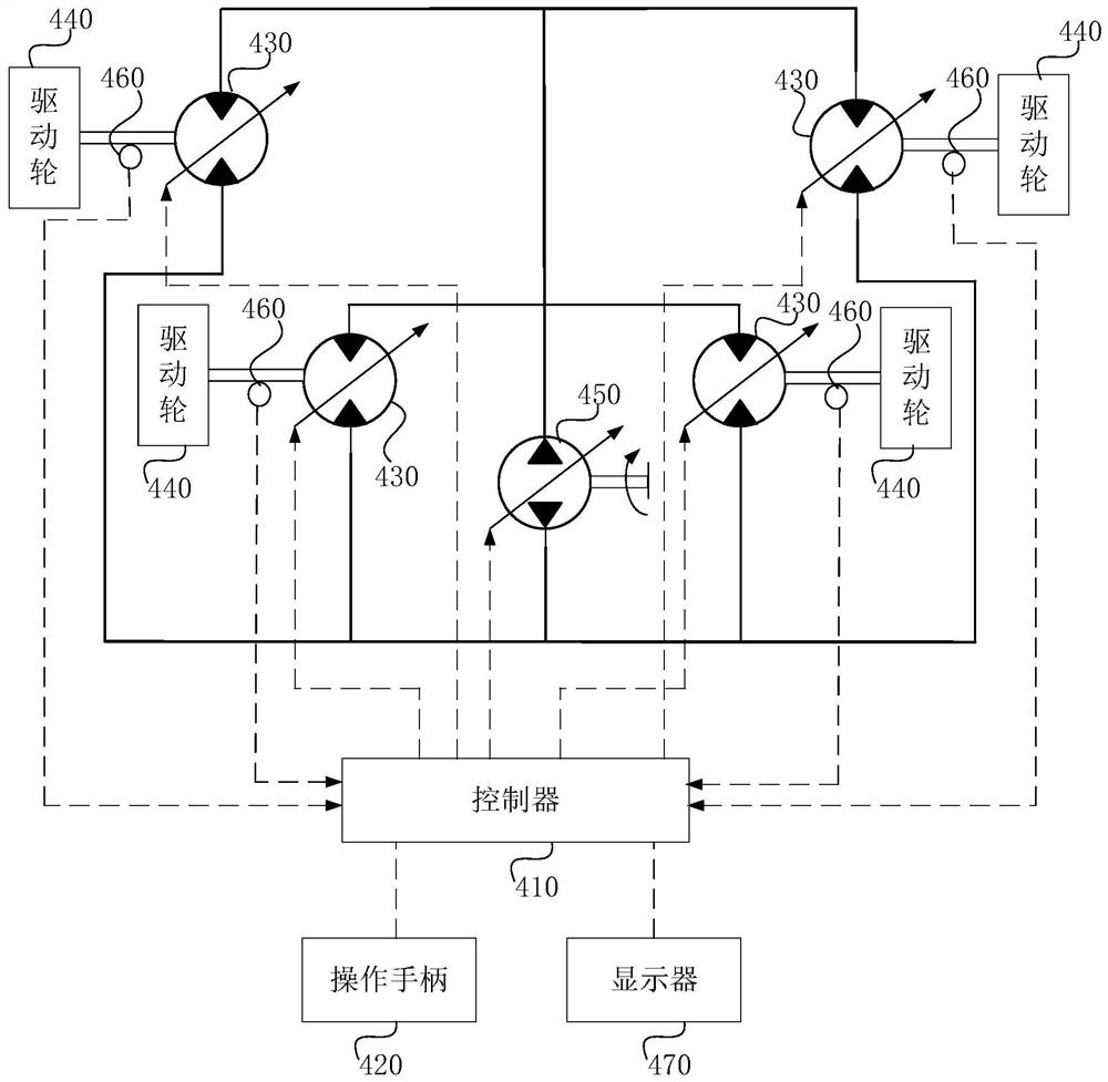
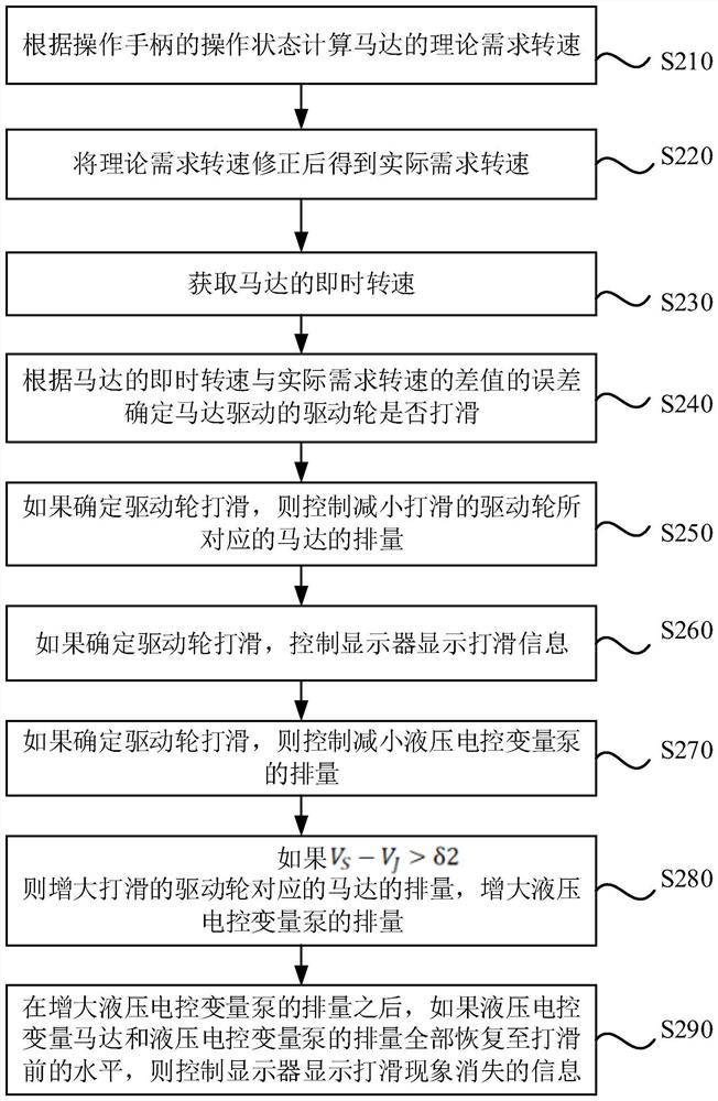
[0043] figure 1 It is a flow chart of a milling machine anti-skid method provided by an embodiment of the present invention, figure 2 It is a schematic structural diagram of a milling machine provided by the embodiment of the present invention. This embodiment is applicable to the situation of anti-skid of the milling machine. See figure 2 , The milling machine includes: a controller 410 , an operating handle 420 , a motor 430 , a driving wheel 440 , a hydraulic and electronically controlled variable pump 450 ,...


PUM


Abstract

The invention discloses an anti-skid method of a milling machine and the milling machine. The anti-skid method of the milling machine comprises the steps of calculating a theoretical required rotating speed of a motor according to an operation state of an operation handle; correcting the theoretical required rotating speed to obtain an actual required rotating speed; obtaining the instant rotating speed of the motor; determining whether a driving wheel driven by the motor slips or not according to the error of the difference between the instant rotating speed and the actual required rotating speed of the motor; and if it is determined that the driving wheel slips, controlling the displacement of the motor corresponding to the slipped driving wheel to be reduced. Whether the vehicle slips or not can be accurately judged, the anti-slip effect is improved, the control stability of a walking system of the milling machine is enhanced, power loss caused by slipping of a walking hydraulic system of the milling machine is avoided, and the milling machine can always maintain high operation efficiency during working.

Description

technical field [0001] The embodiment of the present invention relates to a milling machine control technology, in particular to a milling machine anti-skid method and a milling machine. Background technique [0002] When the vehicle walks on uneven roads, the grip of the wheels is reduced and slipping is prone to occur. Especially for milling machines, the four driving wheels are track wheels. The track wheels do not have the elasticity of rubber tires, so slipping is more likely to occur. [0003] At present, the vehicle anti-skid method is to first judge the slipping phenomenon, obtain the reference value according to the average value of the real-time speed of the four track wheels, compare the real-time speed of the wheel with the reference value to judge the slipping phenomenon, and carry out motor control when the slipping phenomenon occurs. Displacement adjustment to achieve anti-skid. [0004] However, in the existing method for judging the slipping phenomenon, in ...

Claims


Application Information

Patent Timeline
IPC IPC(8): E01C23/08E01C23/12B60L15/20
CPCE01C23/08E01C23/12B60L15/20B60L2240/42B60L2240/421Y02T10/72
Inventor 刘增志刘宏李芳玉李定国刘喜锋何树营桑广波
Owner SHANTUI CONSTR MASCH CO LTD
Learn More