[0021] The present invention will be described in further detail below with reference to the accompanying drawings and embodiments. Wherein the same parts are denoted by the same reference numerals. It should be noted that the words "front", "rear", "left", "right", "upper" and "lower" used in the following description refer to directions in the drawings, and the words "bottom" and "top" ", "inner" and "outer" refer to directions toward or away from the geometric center of a particular part, respectively.
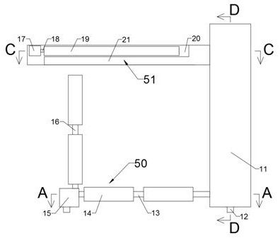
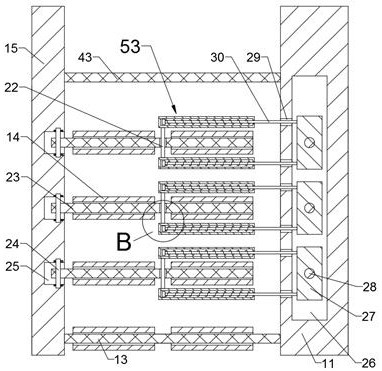
[0022] like Figures 1 to 6 As shown in the figure, the lifting device for the large-scale collapse of the traffic guardrail includes a transmission box 11, and a support device 50 for supporting the collapsed guardrail is provided on the side of the transmission box 11 close to the traffic guardrail. The bottom rod 13 on the end surface of the transmission box 11 is close to the side of the traffic guardrail. The end surface of the bottom rod 13 away from the transmission box 11 is fixedly provided with a support plate 15, and the inner array of the support plate 15 is provided with three rotating Cavity 25, a supporting shaft 24 perpendicular to the bottom rod 13 is rotated between the inner walls on opposite sides of the rotating cavity 25, a supporting rod 23 is fixed on the supporting shaft 24, and the supporting device 50 is kept away from the ground. The side is provided with a positioning device 51 for stably limiting the guardrail, the transmission box 11 is provided with a transmission cavity 26, and the transmission cavity 26 is provided with the support device 50 and the positioning device 51 through the worm gear and worm. The fixed ratio linkage device 54 for the lifting action of the traffic barrier.
[0023] Refer to the attached figure 1 , figure 2 , Image 6 As shown, the support device 50 further includes a contact shaft 16 fixedly arranged on the end face of the support plate 15 away from the ground and located at a position corresponding to the bottom rod 13 on one side. The rod 13 and the three support rods 23 are respectively symmetrical and rotatable with two guide wheels 14; when the fallen traffic guardrail is lifted up, the two guide wheels 14 on the interference shaft 16 interfere with the traffic In the normal area on one side of the guardrail, the two guide wheels 14 on the bottom bar 13 abut against the area on the side where the traffic guardrail falls, and the three support rods 23 swing to realize the lifting of the traffic guardrail.
[0024] Refer to the attached figure 1 , Figure 4 , Image 6 As shown, the positioning device 51 includes a fixing plate 21 that is fixedly arranged on the end surface of the transmission box 11 on one side of the traffic guardrail. A turning shaft 34 is rotated on the inner wall of one side, and a turning plate 17 is fixed on the end surface of the turning shaft 34 near the bottom rod 13 . There are five positioning shafts 18 rotatably provided, and positioning wheels 19 are fixed on the positioning shafts 18 . A transition shaft 35 is rotatably provided in a bearing plate 36 , and the end of the turning shaft 34 away from the bottom rod 13 extends to the side of the fixing plate 21 away from the bottom rod 13 and is conical with the transition shaft 35 Tooth meshing connection, one end of the transition shaft 35 away from the turning shaft 34 extends into the transmission cavity 26 and is rotatably connected with the inner wall of the corresponding side of the transmission cavity 26; when the transition shaft 35 rotates, it drives the turning When the shaft 34 and the turning plate 17 rotate, the positioning shaft 18 and the positioning wheel 19 rotate around the turning shaft 34. When the positioning wheel 19 abuts against the opposite side end face of the side of the traffic guardrail, the The positioning wheel 19 can position the traffic guardrail in the normal state, and prevent the traffic guardrail from being deflected or inverted when being lifted up.
[0025] Refer to the attached figure 2 , Figure 4 , Figure 5 As shown, the fixed-ratio linkage device 54 includes a second bearing plate 41 that is fixedly arranged on the inner wall of the transmission cavity 26 on the side away from the bottom rod 13 , and the transmission cavity 26 is fixedly arranged on the inner wall of the side close to the ground. There is a servo motor 40, and the side end of the servo motor 40 away from the ground is provided with a power worm 38 rotatably connected to the second bearing plate 41, and the second bearing plate 41 is rotatably provided with the transmission A linkage shaft 37 is rotatably connected to the inner wall of the cavity 26 away from the ground. The linkage shaft 37 forms a worm gear and worm connection with the power worm 38 and is in helical meshing connection with the transition shaft 35. The inner wall of the transmission cavity 26 is on the opposite side. Three threaded shafts 28 are arranged in an array and rotate at the corresponding positions of the three supporting rods 23. The threaded shafts 28 are threadedly connected with a threaded plate 27, and the three threaded shafts 28 are connected with adjacent belts and are farthest away from the The threaded shaft 28 on the side of the bottom rod 13 is belt-connected with the linkage shaft 37; when the servo motor 40 is activated, the power worm 38 rotates at a fixed angle, because the power worm 38 and the linkage shaft 37 A worm gear and worm connection are formed, so the power worm 38 and the linkage shaft 37 are unidirectionally driven and self-locked in the opposite direction, that is, the power worm 38 can drive the linkage shaft 37 to rotate, and the linkage shaft 37 drives the thread. The shaft 28 and the transition shaft 35 rotate, but the transition shaft 35 cannot drive the linkage shaft 37 to rotate, so that the positioning of the positioning wheel 19 is more stable.
[0026] Refer to the attached figure 2 , image 3 , Image 6 As shown, the support rod 23 is provided with a lifting device 53 for realizing the lifting action of the guardrail. The lifting device 53 includes two guide wheels 14 rotatably arranged in the support rod 23 and located at corresponding positions. The rotating pin 22 between the two ends of the rotating pin 22 is symmetrical with respect to the corresponding position of the support rod 23 and is fixedly provided with two balancing cylinders 31 . A limit slider 32 is slid inside, a lift rod 30 is fixed on the end face of the limit slider 32 away from the support plate 15 , and the limit slider 32 is away from the support plate 15 on the end face A balance spring 33 is fixed between the balance chamber 42 and the inner wall of the side of the balance chamber 42 away from the support plate 15 . It is fixedly connected with the end face of the threaded plate 27 on the side close to the support plate 15 at the corresponding position, and the transmission cavity 26 is close to the support plate 15. The lifting rod 30 is provided with six stroke grooves 29 in the corresponding position, and the lifting rod 30 can slide in the stroke groove 29 at the corresponding position; when the threaded plate 27 moves on the threaded shaft 28, the The lifting rod 30 drives the balance cylinder 31 to move to the side away from the ground, the rotation pin 22 drives the support rod 23 to swing to the side away from the ground, and the rotation pin 22 rotates relative to the support rod 23 . The limit slider 32 slides in the balance cavity 42 to adapt to the distance between the rotation pin 22 and the threaded plate 27, the balance spring 33 is compressed, and the swing of the support rod 23 can give the fallen guardrail Lifting force, so as to realize the support of the guardrail.
[0027] Refer to the attached Figure 4 , Figure 5 , Image 6 As shown in the figure, a fixed rod 43 is fixed between the transmission case 11 and the support plate 15, and the power worm 38 drives the linkage shaft 37 to rotate during one rotation cycle of the power worm 38, and the linkage shaft The rotation of 37 drives the transition shaft 35 to rotate, and the transition shaft 35 just drives the flip shaft 34 and the flip plate 17 to rotate two hundred and seventy degrees in one rotation cycle, that is, the positioning wheel 19 rotates just two hundred and seventy degrees. Seventy degrees collides with the end face on the opposite side of the guardrail, and the transmission ratio between the linkage shaft 37 and the three power worms 38 decreases step by step, that is, the linkage shaft 37 is connected by a belt to drive the farthest away from the The number of turns of the threaded shaft 28 on the side of the bottom rod 13 is greater than the number of turns of the threaded shaft 28 in the middle position, and the number of turns of the threaded shaft 28 in the middle position is greater than that on the side closest to the bottom rod 13. The number of revolutions of the threaded shaft 28, when the three threaded shafts 28 are rotated, the distance that the three threaded plates 27 move to the side away from the ground gradually along the direction from the bottom rod 13 to the fixed rod 43 Raised, after one rotation cycle of the power worm 38 is completed, the support rod 23 on the side closest to the bottom rod 13 is rotated by 22.5 degrees, and the support rod 23 at the middle position is rotated by 45 degrees. The support rod 23 on the side farthest from the bottom rod 13 rotates by 67.5 degrees, and the transmission box 11 and the support plate 15 are respectively provided with four moving cavities on the side close to the ground. 39. A roller 12 is rotated in the moving cavity 39, and the end face of the transmission box 11 away from the support plate 15 is externally connected to a moving carrier; when the moving carrier drives the transmission box 11 to move, because the bottom rod 13 , the angular relationship between the three support rods 23 and the interference shaft 16, the fallen guardrail will be lifted up along the angles of the ten guide wheels 14. Since the guardrail is in a continuous state, the guide wheels 14 can continuously drive the guardrail to restore the working state with the movement of the mobile carrier.
[0028] working principle:
[0029] Initially, the end face of the threaded plate 27 on the side close to the ground collides with the inner wall of the transmission cavity 26 on the side close to the ground, the positioning wheel 19 collides with the inner wall of the turning cavity 20 on the side close to the ground, the three support rods 23 are parallel to the bottom rod 13, and the balance cylinder 31 Parallel to the support rod 23, the limit slider 32 is located in the balance chamber 42 on the side closest to the support plate 15, and the balance spring 33 is not compressed;
[0030] In preparation, the two guide wheels 14 on the collision shaft 16 are controlled by moving the carrier to interfere with the normal area on the side of the traffic guardrail, and the two guide wheels 14 on the bottom bar 13 contact the area on the side of the traffic guardrail, and the servo motor 40 is activated to drive The power worm 38 completes a rotation cycle, the power worm 38 drives the linkage shaft 37 to rotate, the linkage shaft 37 rotates to drive the transition shaft 35 to rotate, and the transition shaft 35 just drives the turning shaft 34 and the turning plate 17 to rotate 270 degrees in one rotation cycle. That is, the positioning wheel 19 just rotates 270 degrees and collides with the end face on the opposite side of the guardrail. The rotation of the linkage shaft 37 drives the three threaded shafts 28 to rotate. , The rotation pin 22 moves to the side away from the ground, the rotation pin 22 drives the support rod 23 to swing to the side away from the ground, and the rotation pin 22 rotates relative to the support rod 23, and the limit slider 32 slides in the balance cavity 42 to adapt to the rotation pin 22 The distance between the threaded plate 27 and the balance spring 33 is compressed. Due to the transmission ratio relationship between the linkage shaft 37 and the three threaded shafts 28, the three threaded plates 27 move to the side away from the ground at different distances. When the power worm 38 After one rotation cycle is completed, the supporting rod 23 on the side closest to the bottom rod 13 rotates 22.5 degrees, the supporting rod 23 in the middle position rotates 45 degrees, and the supporting rod 23 on the side farthest from the bottom rod 13 rotates 67 points. fifth degree;
[0031] During operation, the moving carrier is used to drive the transmission box 11 and the support plate 15 to move in the direction of the guardrail. Due to the angular relationship between the bottom rod 13 , the three support rods 23 and the interference shaft 16 , the fallen guardrail will follow the ten guide wheels 14 Since the guardrail is in a continuous state, the guide wheel 14 can continuously drive the guardrail to restore the working state with the movement of the moving carrier. Each device in the transmission line will return to the initial state.
[0032] The above technical solutions only represent the preferred technical solutions of the technical solutions of the present invention, and some changes that those skilled in the art may make to some parts of them all reflect the principles of the present invention and fall within the protection scope of the present invention.