Automatic waste cleaning and recycling device

An automatic cleaning and recycling device technology, applied in road cleaning, cleaning methods, construction and other directions, can solve the problems of low waste cleaning and recycling efficiency, waste of manpower, etc., to achieve fast and effective cleaning, improve work efficiency, and facilitate transportation and recycling.

Inactive Publication Date: 2021-06-25
HUAIAN COLLEGE OF INFORMATION TECH
View PDF5 Cites 0 Cited by
  • Summary
  • Abstract
  • Description
  • Claims
  • Application Information

AI Technical Summary

Problems solved by technology

[0003] The purpose of the present invention is to provide an automatic cleaning and recovery device for waste materials, which aims to improve the existing methods of cleaning and recycling waste materials. Most of them use manual cleaning of waste materials, and then use containers to load waste materials and then transfer them. This method has low cleaning and recovery efficiency for waste materials. and will waste a lot of manpower

Method used


Image

  • Automatic waste cleaning and recycling device
  • Automatic waste cleaning and recycling device
  • Automatic waste cleaning and recycling device

Examples


Embodiment 1

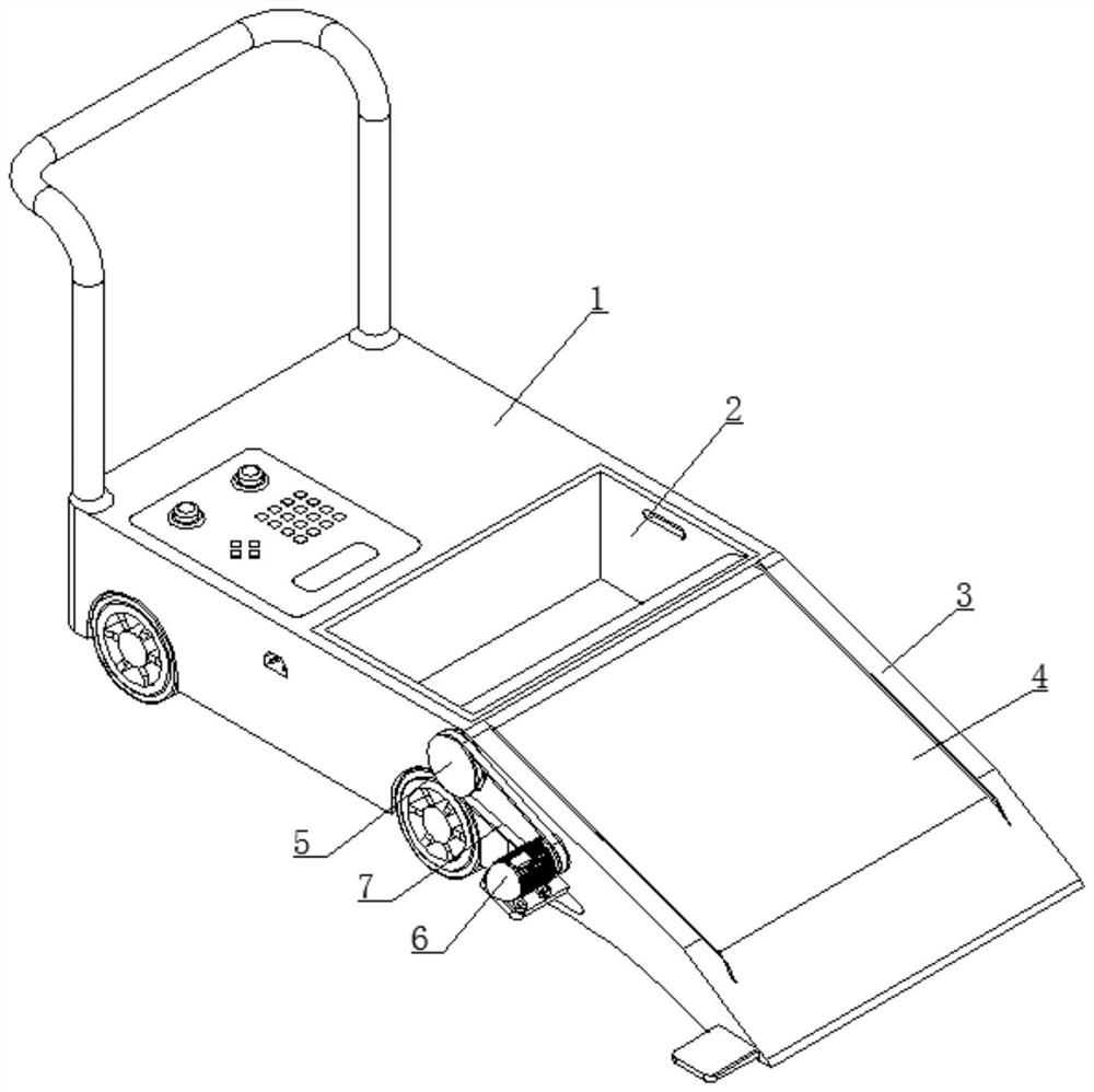
[0031] refer to figure 1Shown: an automatic cleaning and recovery device for waste materials, including a transfer vehicle 1, a storage box 2 is provided inside the transfer vehicle 1 near the front end, and a conveying mechanism including a mounting frame 3, a conveyor belt 4, a transmission shaft 5, The first motor 6 and the first belt 7, the top of the installation frame 3 is against the front end of the transfer vehicle 1, and the installation frame 3 and the transfer vehicle 1 are connected together by bolts, the inside of the installation frame 3 is provided with a conveyor belt 4, and the output belt inside two Both ends are provided with a drive shaft 5, and one end of the drive shaft 5 that is arranged on the top of the conveyor belt 4 protrudes out of the mounting frame 3, and the side of the mounting frame 3 is aligned with the position of the end of the drive shaft 5 protruding out of the body to be provided with a first motor 6, the first The output end of the mot...

Embodiment 2

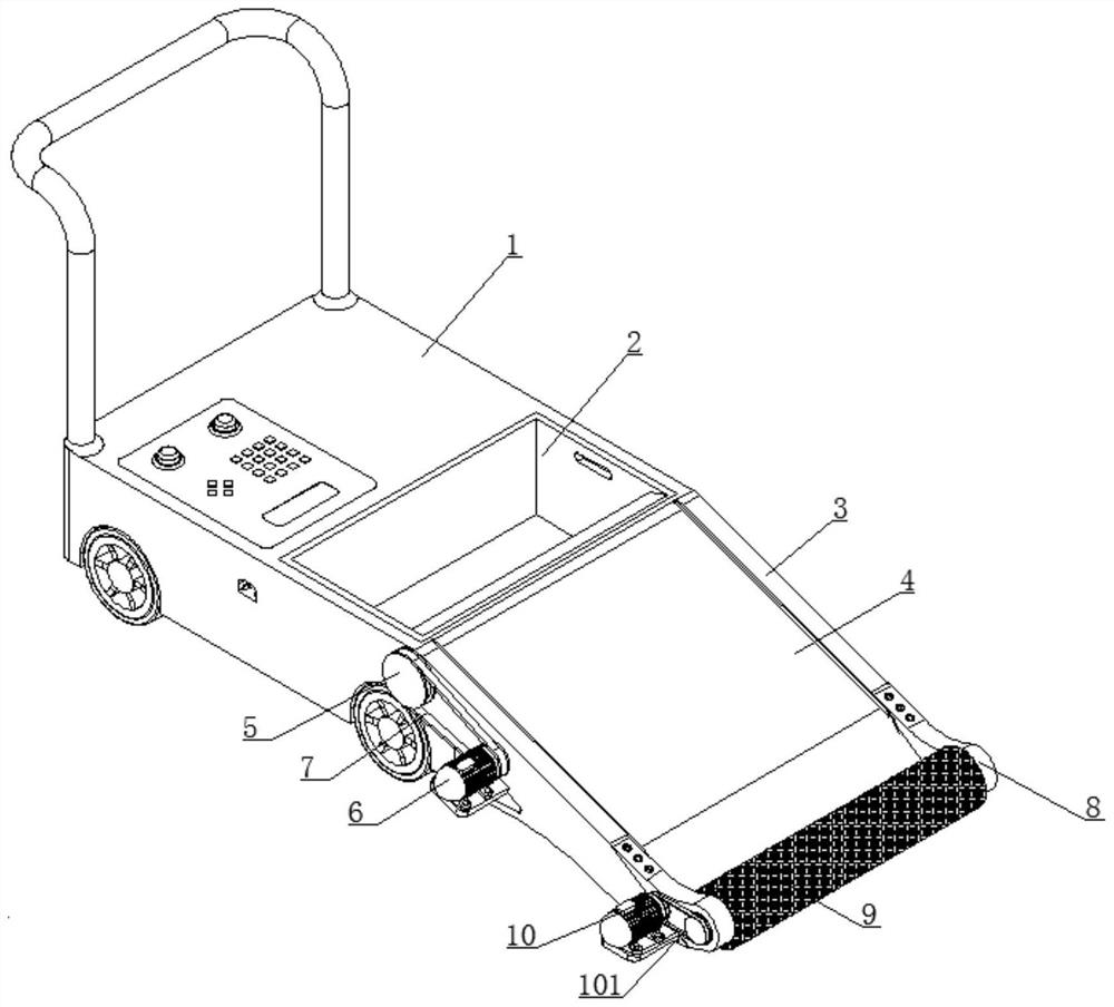
[0039] refer to figure 2 Shown: an automatic cleaning and recovery device for waste materials, including a transfer vehicle 1, a storage box 2 is provided inside the transfer vehicle 1 near the front end, and a conveying mechanism including a mounting frame 3, a conveyor belt 4, a transmission shaft 5, The first motor 6 and the first belt 7, the top of the installation frame 3 is against the front end of the transfer vehicle 1, and the installation frame 3 and the transfer vehicle 1 are connected together by bolts, the inside of the installation frame 3 is provided with a conveyor belt 4, and the output belt inside two Both ends are provided with a drive shaft 5, and one end of the drive shaft 5 that is arranged on the top of the conveyor belt 4 protrudes out of the mounting frame 3, and the side of the mounting frame 3 is aligned with the position of the end of the drive shaft 5 protruding out of the body to be provided with a first motor 6, the first The output end of the m...


PUM


Abstract

The invention discloses an automatic waste cleaning and recycling device which comprises a transfer trolley, a storage box is arranged at the position, close to the front end, in the transfer trolley, the automatic waste cleaning and recycling device further comprises a conveying mechanism, the conveying mechanism comprises a mounting frame, a conveying belt, a transmission shaft, a first motor and a first belt, the top end of the mounting frame is against the front of the transfer trolley, the mounting frame and the transfer trolley are connected together through bolts, the conveying belt is arranged on the inner side of the mounting frame, transmission shafts are arranged at the two ends of an output belt, and one end of the transmission shaft arranged at the top end of the conveying belt extends out of the mounting frame. The invention solves the problems that during existing waste material cleaning and recycling, waste materials are manually cleaned, then the waste materials are loaded by a container and transferred, waste material cleaning and recycling efficiency is low and a large amount of manpower is wasted. The structure of the cleaning and recycling device is improved and optimized, so that the cleaning and recycling device can quickly clean the waste materials, and the swept waste materials can be conveyed into a temporary storage container while the waste materials are swept.

Description

technical field [0001] The invention relates to the technical field of cleaning and recycling equipment, in particular to an automatic cleaning and recycling device for waste materials. Background technique [0002] Nowadays, many industries will produce a lot of waste in the process of producing products, and these wastes can be reused after recycling. Some common wastes that can be recycled, such as iron filings, cloth and plastic particles, etc., so factories often use Arrange staff to clean and transfer the waste generated by production, and then centralize the treatment so that the waste can be reused and effectively save resources. However, the existing devices for cleaning and recycling waste have the following problems: the existing way of cleaning and recycling waste Most of the waste is cleaned manually, and then the waste is loaded into the container and then transferred. This method of waste cleaning and recovery is inefficient and will waste a lot of manpower. ...

Claims


Application Information

Patent Timeline
Patent Type & Authority Applications(China)
IPC IPC(8): E01H1/05E01H1/00
CPCE01H1/056E01H1/00
Inventor 喻步贤刘俊叶畅
Owner HUAIAN COLLEGE OF INFORMATION TECH
Why Eureka
Try Eureka