
Air inlet type self-circulation filter

A self-circulation and filter technology, applied in gravity filter, loose filter material filter, filter separation, etc., can solve the problems of filter material tumbling, high pollutant concentration, and increase the difficulty of personnel operation, so as to improve the water output Effects of water quality, improvement of use efficiency, and reduction of use restrictions

Pending Publication Date: 2018-02-16
重庆林德科技发展有限公司
View PDF5 Cites 0 Cited by
  • Summary
  • Abstract
  • Description
  • Claims
  • Application Information

AI Technical Summary

Problems solved by technology

[0002] In the current filter, a high-pressure pump needs to be equipped in front of the filter to provide sufficient filtration pressure, and the filter tank must be a closed structure, and cannot withstand high pollutant concentrations during operation. , which increases the use limit of the equipment; when the filter is cleaning the filter material, it needs to be shut down for operation, which increases the difficulty of personnel's operation and the operating efficiency of the equipment; and in the cleaning process, when the filter material layer is thicker, When the filter material particles are large, the washing water cannot effectively roll and clean the filter material, resulting in incomplete cleaning of the filter material, which in turn causes the water production to fail to achieve the intended effect

Method used


Image

  • Air inlet type self-circulation filter
  • Air inlet type self-circulation filter
  • Air inlet type self-circulation filter

Examples


Embodiment Construction

[0016] The preferred embodiments of the present invention will be described in detail below with reference to the accompanying drawings.

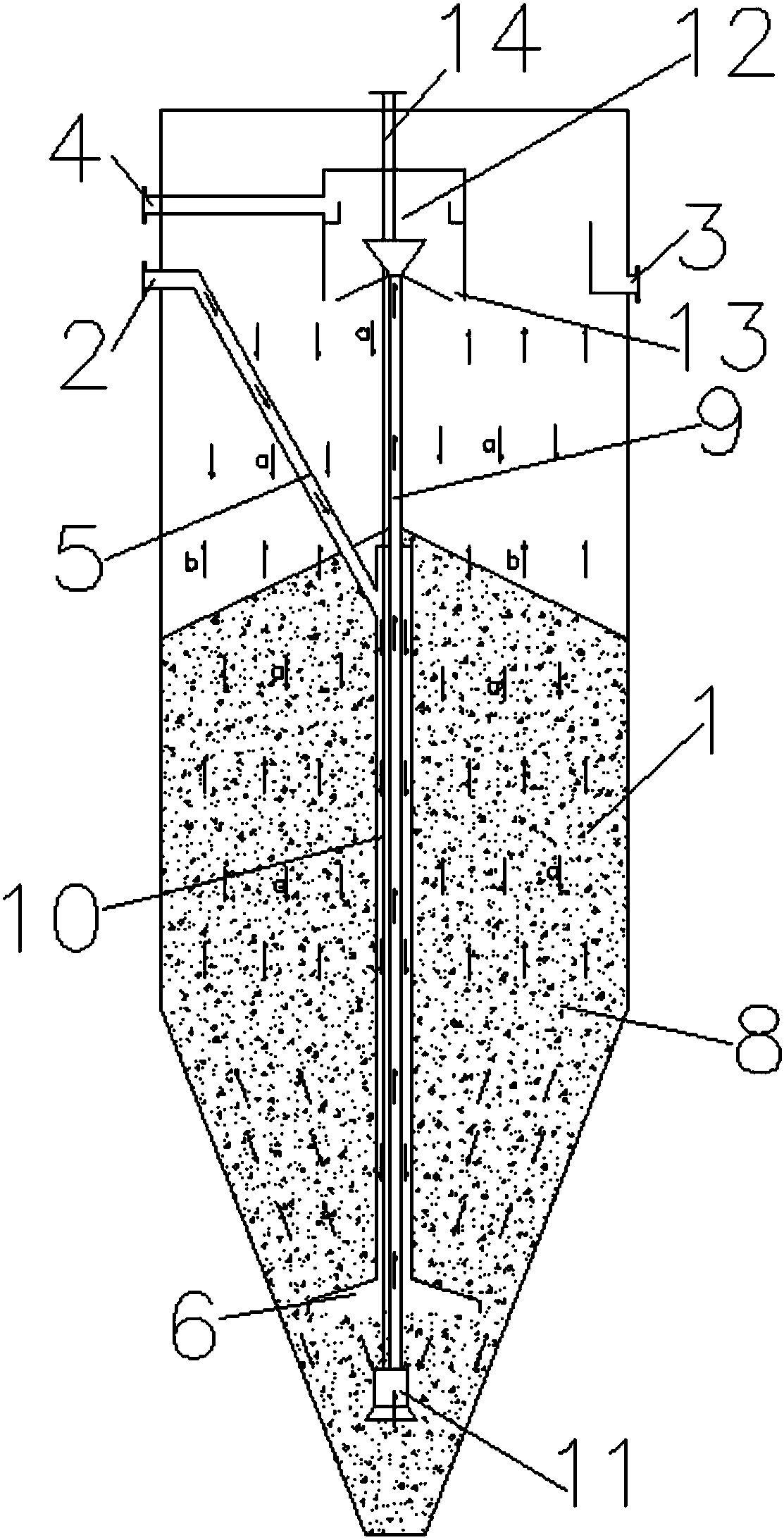
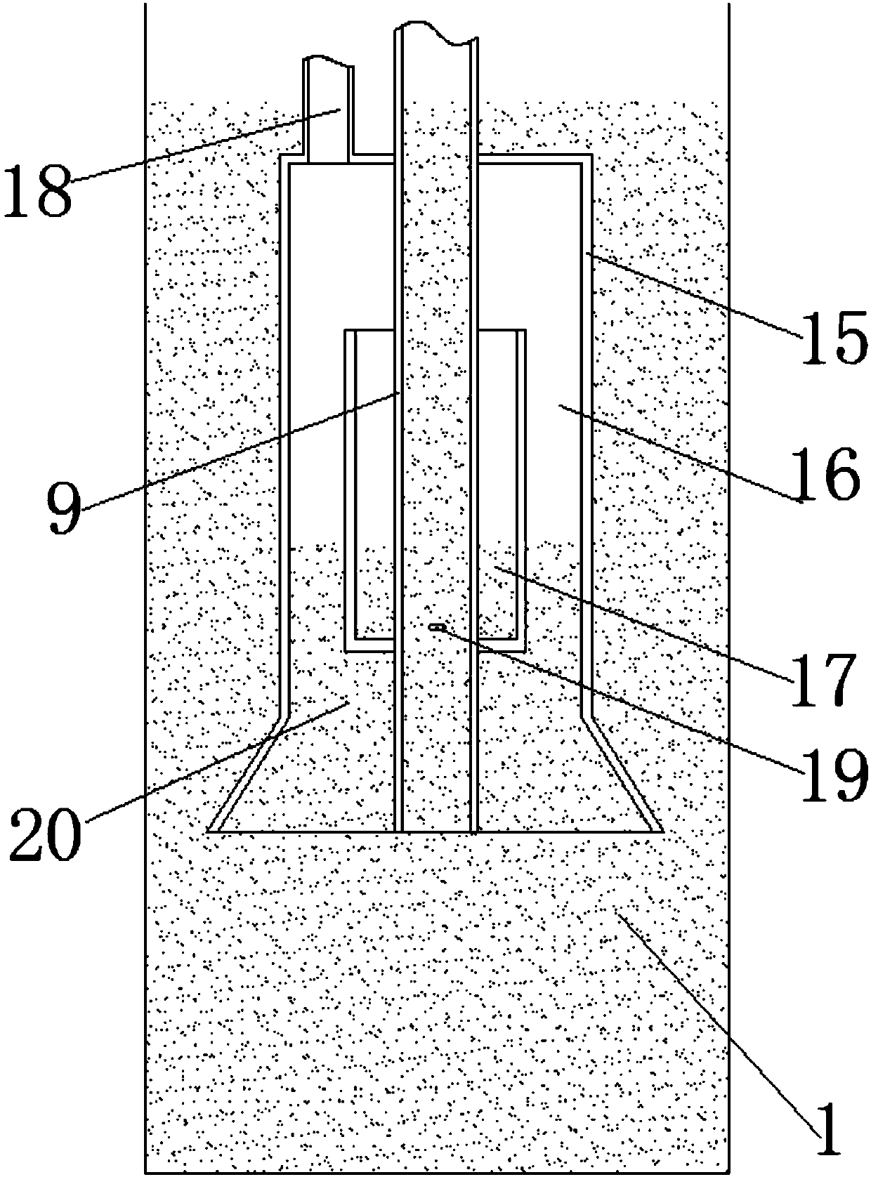
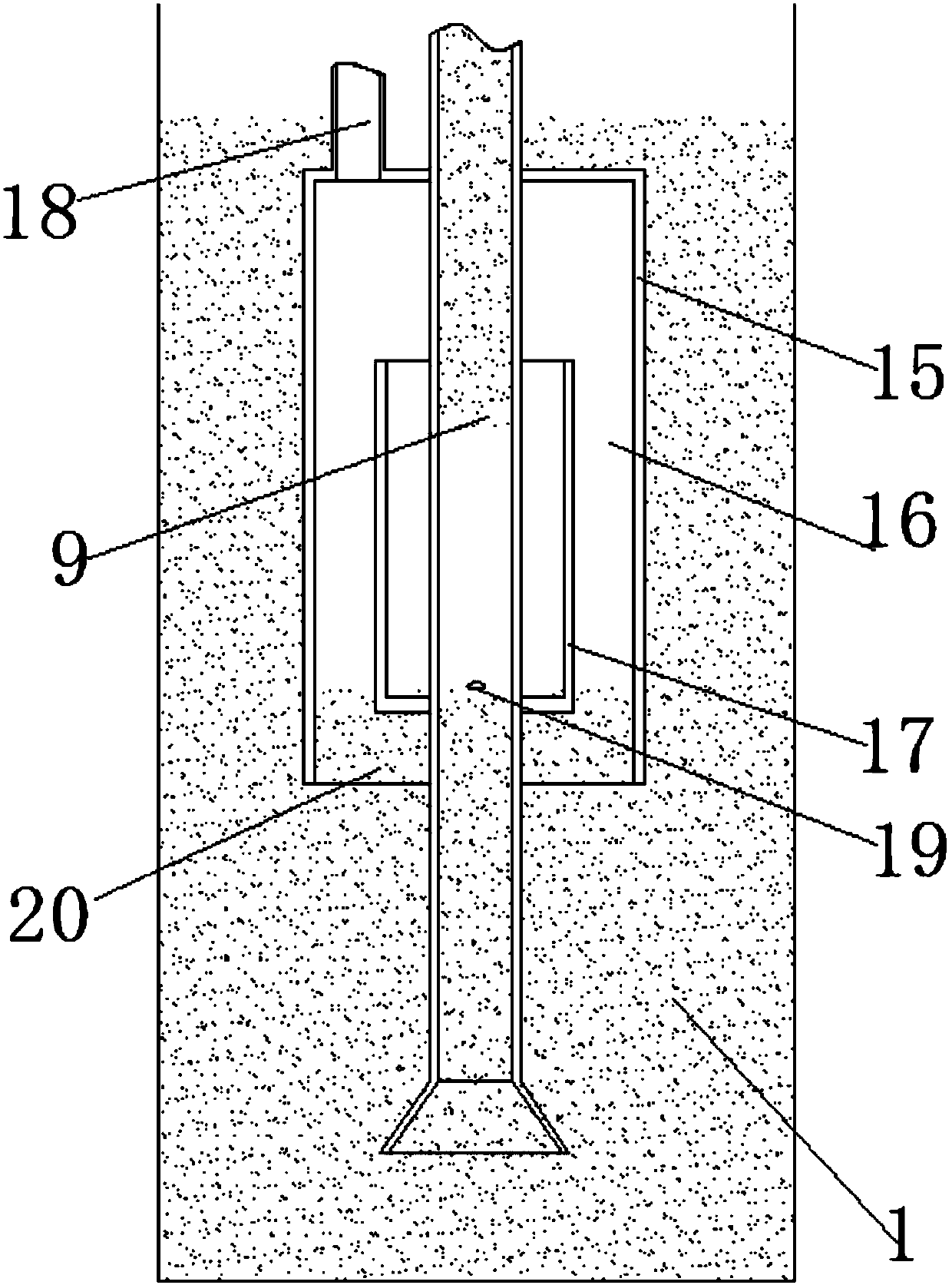
[0017] Such as Figure 1-2 Shown is a schematic structural view of the air-intake self-circulation filter of the present invention; an air-intake self-circulation filter of the present invention includes a body 1, a water inlet 2 and a water outlet 3 arranged on the upper side wall of the body 1 , the body 1 is connected with an air intake pipe 14, the bottom of the body 1 is provided with a filter bin 7, the water outlet 3 communicates with the top of the filter bin 7, and the body 1 is provided with a water inlet 2 connected water inlet pipe 5, the water inlet pipe 5 is connected with a vertical pipe 10, the vertical pipe 10 is arranged in the middle of the body 1, and the bottom of the vertical pipe 10 is provided with a water distributor connected with the lower part of the filter material bin 7 6. The filter material suction pipe 9 is...


PUM


Abstract

The invention discloses an air inlet type self-circulation filter, which comprises a filter body, a water inlet, a water outlet and an air inlet pipe, wherein a filtering material cabin is arranged atthe bottom of the filter body; the water outlet communicates with the upper side of the filtering material cabin; a water inlet pipe is arranged in the filter body and communicates with a vertical pipe; the vertical pipe is arranged at the middle part of the filter body; a water distributor is arranged at the bottom of the vertical pipe; a filtering material sucking pipeline is arranged in the vertical pipe in a sleeving way; a pulse type lifting pump is arranged at the bottom of the filtering material sucking pipeline; the top of the filtering material sucking pipeline is provided with a filtering material sucking device and a filtering material outlet; a filtering material cleaner is arranged at the filtering material outlet. The pulse type lifting pump and the filtering material cleaner are arranged in the filter; sewage and filtering materials at the inner bottom of the filter are lifted to the filtering material cleaner at the upper side for cleaning; after the cleaning is completed, filtering materials fall onto the upper part of the filter to continuously operate, so that the filtering materials in the filter are cyclically used and cleaned; the filtering material use efficiency and the filtering material cleaning degree are improved; the water outlet quantity is increased; the water outlet water quality is improved.

Description

technical field [0001] The invention belongs to the technical field of filters, and in particular relates to a high-efficiency air-intake self-circulation filter in sewage treatment. Background technique [0002] In the current filter, a high-pressure pump needs to be equipped in front of the filter to provide sufficient filtration pressure, and the filter tank must be a closed structure, and cannot withstand high pollutant concentrations during operation. , which increases the use limit of the equipment; when the filter is cleaning the filter material, it needs to be shut down for operation, which increases the difficulty of personnel's operation and the operating efficiency of the equipment; and in the cleaning process, when the filter material layer is thicker, When the filter material particles are large, the washing water cannot effectively roll and clean the filter material, resulting in incomplete cleaning of the filter material, which in turn causes the water product...

Claims


Application Information

Patent Timeline
Patent Type & Authority Applications(China)
IPC IPC(8): B01D24/30B01D24/46
CPCB01D24/30B01D24/46
Inventor 李渝
Owner 重庆林德科技发展有限公司
Learn More