Environment-friendly and energy-saving rammer for building construction
A building construction and energy-saving technology, which is applied in construction, soil protection, infrastructure engineering, etc., can solve the problems of poor energy conservation and environmental pollution by rammers, and achieve the goals of improving environmental protection, avoiding environmental pollution, and reducing energy consumption. Effect
- Summary
- Abstract
- Description
- Claims
- Application Information
AI Technical Summary
Problems solved by technology
Method used
Image

Examples
Embodiment
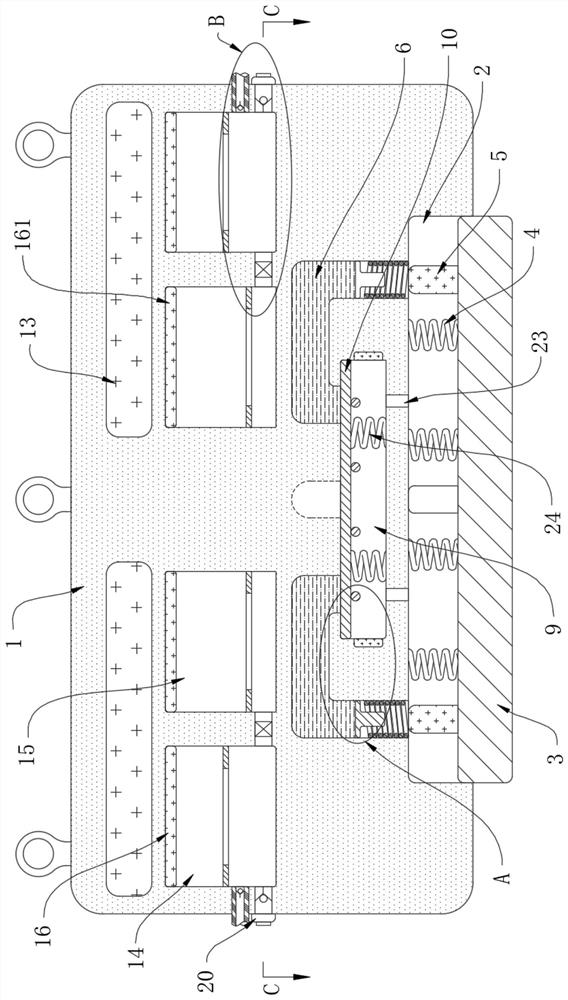
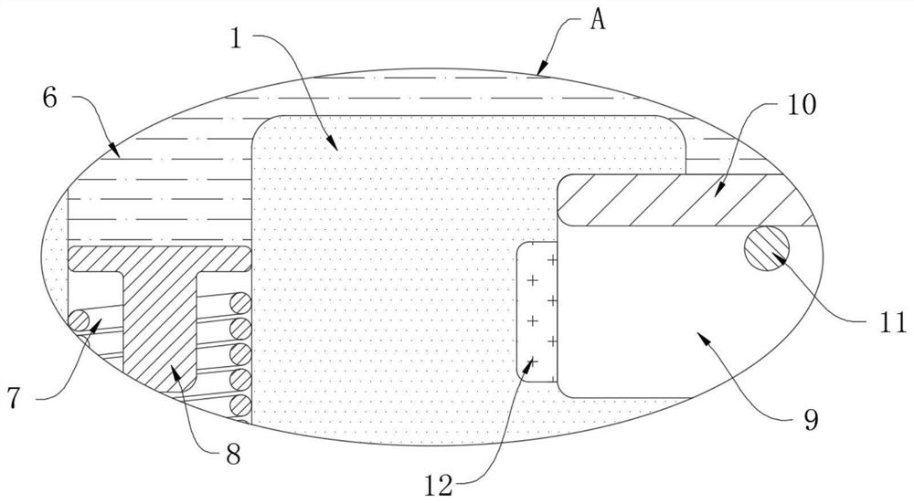
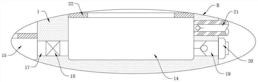
[0022] refer to Figure 1-4 , an environment-friendly and energy-saving rammer for building construction, comprising a rammer main body 1, the lower surface of the rammer main body 1 is sleeved with a steel plate 3 through a sliding groove 2 for damping sliding, wherein two opposite side walls are damping and slidingly sleeved, and the other two One side wall is not in contact with the inner side wall of the sliding groove 2, that is, the sliding groove 2 is kept in communication with the outside world, a number of connection springs 4 are fixedly connected between the steel plate 3 and the inner top wall of the sliding groove 2, and a plurality of magnetic columns 5 are welded on the upper surface of the steel plate 3 , the inner top wall of the sliding groove 2 is provided with a U-shaped hole 6, and there are four U-shaped holes 6 with an angle of 90° between each. There is a functional chamber 9, the U-shaped hole 6 communicates with the sliding groove 2 and the functional...
PUM
 Abstract
Description
Claims
Application Information